Download
1 / 20
200 likes | 382 Views
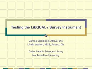
Instrument testing and monitoring. David Teyssier – HPST - ESAC. Overview. IEGSE and QLA SCOS2000 QLA ILT Operations Database management and software support Test scripts and instrument configuration ILT Data Analysis The requirements The tools. IEGSE.

E N D
Instrument testing and monitoring David Teyssier – HPST - ESAC
Overview • IEGSE and QLA • SCOS2000 • QLA • ILT Operations • Database management and software support • Test scripts and instrument configuration • ILT Data Analysis • The requirements • The tools Instrument testing and monitoring
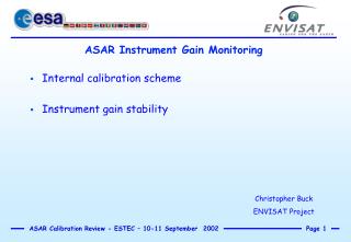
IEGSE • All ILT are run under the ESA SCOS2000 environment. It provides the tools for: • Commanding the instrument (TOPE: launch test/observing mode, MSTK: manual TC) • Monitoring the instrument and test status: out-of-limit check and warning display, TC history and monitoring, HK monitoring, TM packet monitoring • It is the same environment as will be used by ESA during the mission • SCOS2000 is maintained on the test machines by AdJ • System working smooth, some upgrades needed from time to time Instrument testing and monitoring
SCOS2000: one example TOPE command window Instrument testing and monitoring
QLA • Several QLAs developed in the framework of HIFI ILT • wbsqla for WBS monitoring (resp. A. Lorenzani). • hrsnewqla for HRS monitoring (resp. O. Coeur-Joly) • ivScanViewAppl for IV-curve monitoring (resp. G. Wiersma) • beamprofile for beam measurement (resp. J. Corrales) • HKplotter to monitor any kind of HK (resp. P. Zaal) • QLAs are part of the HIFI build, so they are automatically available in the HCSS environment • Main features: • WBS: live and replay of total power WBS spectra, computation of IF noise and gain, receiver noise and gain, Y-factor. • HRS: live and replay of total power HRS spectra, computation of IF noise and gain, receiver noise and gain, Y-factor, IF total power. • IVcurve: live and replay of mixer IV curve plot Instrument testing and monitoring
IV curve QLA example QLA: one example Instrument testing and monitoring
QLA • QLA applications have been significantly improved during DM and QM campaign. Efficient communication with developers • They are felt to offer sufficient support for the immediate quick-look of all spectroscopic data. Improvement always possible on-the-fly (SPR/SCR). • Open issues: • QLA for beam measurements currently not tested on real data (beam scanner has just started to be operational). No clear whether beam scanner will be operated from SCOS or SCOE, so that the QLA may not be used for ILT • HKplotter not routinely used. Further development unclear • ESA (HSCDT) is working on generic tools to manage HK and calibration products. Maybe used as generic HK plotter • QLA documentations available. Instrument testing and monitoring
ILT Operations • ILT activities lead by AIV manager, and a team of test engineers for dedicated topic. In principle, tests conducted by test operator (N. Bruning) • ICC contributions are: • Software maintenance (IEGSE, QLA): see previously • Database management (resp. AdJ, P.Zaal): • Database are created and set-up for each sub-campaign (e.g. QM, DM2) • Database are regularly exported to the ICC computer cluster to allow off-line analysis • Test scripts and instrument configuration parameters: CUS scripts (resp. D. Teyssier) Instrument testing and monitoring
ILT Operations: test scripts • Tests (goal, sequence, etc) are originally defined by AIV team, instrument scientist, test engineers • Consequently, dedicated test equipments are designed and built, and test scripts are prepared • The test scripts are coded in the Common Uplink Systemlanguage (CUS), developed by ESA • Allows a uniform approach for the definition of instrument observing modes • Can be commonly used for both pre-flight and in-orbit routine or engineering observations • Many modules prepared for the ILT can be re-used after launch • Most observing sequence can be exercised on real hardware on the ground Instrument testing and monitoring
ILT Operations: test scripts • Tests organized by test (or observing, in flight) modes, consisting of specific building blocks and instrument commands • Instrument command definitions are provided by the MIB (resp. L. Dubbeldam) • Instrument parameters (configuration and calibration) are passed through ascii look-up tables read within the CUS. Interpolation possible (e.g. for frequency dependence) • Input parameters of modes representative of proposal interface (HSPOT) to allow uniformity between test and observing modes • HIFI band in use • HRS resolution mode • Frequency • Others depending on specific test Instrument testing and monitoring
ILT Operations: test scripts // HRS attenuator tuning, mode mode Testmode_HRS_tune { string band="Ia"; // HIFI band string[] hrs_mode = ["wb2","wb2"]; //HRS resolution code }{ StartMode () ; HRS_tune_block_fm (band,hrs_mode) ; //Check final attenuator settings Configure_Spectrometer_proc_fm(band,2.0); Spectro_total_power_block_fm(2.0); StopMode () ; } // HRS attenuator tuning, block // Both polarizations are treated block HRS_tune_block_fm HIFI3601 { string band="Ia"; // HIFI band string[] hrs_mode = ["wb2","wb2"]; //HRS resolution code }{ Start_block(); //Now tune attenuators: it sets the HRS to ultra_wide Hifi_HIFI_Tune_HRS($BBID); delay(6); //Based on empirical experience //Go back to the initial resolution mode HRS_config_resol_fm(band,hrs_mode); //Has its own delays // } Instrument testing and monitoring
Preparing for tests: CUS # Diplexer settings for band 3, QM # Frequency table to be filled.. # DT 25 Oct 2004 double double double freq diplex_h diplex_v 794 -0.845 -0.657 796 0.52 0.82 800 -0.05 0.255 806 -0.845 -0.657 807 0.683 -0.82 # Settings for WBS. Laser1 on/Laser2 off # Considers all 4000 pixels over 4GHz # DT 21 Sep 2004 string double string name value value_string hwh_laser1_s 1.0 On hwh_laser2_s 0.0 Off hwh_heater 0.0 x hwh_latchup_s 1.0 Level1 hwh_att_band4 0.0 x hwh_att_band3 2.0 x hwh_att_band2 4.0 x hwh_att_band1 7.0 x hwh_att_in 11.0 x hwv_laser1_s 1.0 On hwv_laser2_s 0.0 Off hwv_heater 0.0 x hwv_latchup_s 1.0 Level1 hwv_att_band4 7.0 x hwv_att_band3 7.0 x hwv_att_band2 7.0 x hwv_att_band1 7.0 x hwv_att_in 15.0 x wbs_config_delay 2.0 x Example of configuration files Instrument testing and monitoring
ILT Operations: test scripts • CUS scripts are made available through releases posted on the internal ICC webpages, (http://www.sron.rug.nl/hifi_icc/protected/documentation/cus/) • Consists of script (*.cus) and configuration (*.config) files, as well as installation files (*csh files) • A CUS release is generally associated to a MIB, not necessarily released in sync. MIB release can be fetched by ftp (ftp://ftp.sron.nl/pub/lucd/HIFI_MIB). MIB implementation is done by the ICC • It is also associated to a version of the OBSW (resp. AdG). Available functionalities of CUS depend upon those in OBSW. Instrument testing and monitoring
ILT Operation: test scripts • Status for FM: • Unofficial release FM_CUS_1.0 is being developed (very close to completion). Described in “CUS scripts for HIFI FM ILT”. • This CUS has been re-worked to be compatible with the AOT CUS approach for instrument calibration and configuration tables. Use of common modules to uplink parameters. • Missing items: • Multi-frequency/parameter tests (i.e. same test repeated at various frequency), but concatenation of single modes may be possible (AdJ) • LO and mixer (magnet) tuning not yet implemented. Very little control of LO S/S so far • Some functionalities not yet tested in the OBSW, thus missing in CUS • Some test equipment cannot be commanded from SCOS (missing TEI, missing command) Instrument testing and monitoring
ILT data analysis • During test execution, besides of QLA, several tools allow to monitor the test progress • HK: very extensive set of HK is monitored and stored in the database. Can be replayed, and dedicated plot of any HK vs time or another HK can be prepared • Sub/system simulator allows to store every single command stored by the ICU, efficient tools for in-depth analysis • Open issue: • we have been asked to provide tools for automatic check of HK (resp. L. Dubbeldam). Considered feasible, implementation not clear though Instrument testing and monitoring
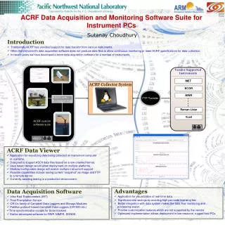
ILT data analysis • After test execution, data are stored in the current database, then exported to the ICC computer cluster • Analysis possible both from test machine (on-line) and ICC machines (off-line) • So far, IA code have been produced by test engineers and other scientists of the ICC (mainly T. Marston, V. Ossenkpof, D. Teyssier) • These codes offer a handful of tasks allowing most of the basic analysis of ILT measurements. They allow to derive most of the instrument parameters, but do not cover all the needs for FM and flight Instrument testing and monitoring
ILT data analysis • ILT IA requirements have been gathered in a document (HIFI ILT IA use cases, ICC/2005-005). • 49 UC identified so far • Based on existing IA tools previously written by T.Marston and V.Ossenkopf • All these tools will be re-used for flight operations (engineering and calibration measurements) • Final IA scripts should contain the latest pipeline for backend data reduction (up to total power spectra, not necessarily calibrated) • Due before start of FM campaign. Status unknown. Instrument testing and monitoring
ILT data analysis: examples Diplexer scan Chopper scan Instrument testing and monitoring
ILT data analysis: examples Instrument noise temperature HRS-H – 901 GHz WBS-H – 901 GHz Instrument testing and monitoring
ILT data analysis: SPR/SCR • Consequent to test execution and/or analysis, SPR/SCR are raised at either ESA or HIFI level • Efficient way to communicate problems/progress over the teams • After problem solved, new software (usually new build) is installed • SPR/SCR are regularly checked by a CCB, trying to stress out where actions should be taken and close obsolete requests. Instrument testing and monitoring