Download
1 / 7
110 likes | 445 Views
Figures for Chapter 16 CROS, bone conduction and implanted aids. Dillon (2001) Hearing Aids. CROS. Better ear. Poorer ear. Figure 16.1 Block diagram of a CROS hearing aid system, viewed from above the head. . Source: Dillon (2001): Hearing Aids. CROS prescription.

E N D
Figures for Chapter 16CROS, bone conduction and implanted aids Dillon (2001) Hearing Aids
CROS Better ear Poorer ear Figure 16.1 Block diagram of a CROS hearing aid system, viewed from above the head. Source: Dillon (2001): Hearing Aids
CROS prescription Figure 16.2 Coupler gain prescriptions for BTE and ITE hearing aids at used volume control setting for a CROS hearing aid. For the BTE hearing aid, a tube fitting is assumed. For the ITE hearing aid, a Janssen fitting is assumed. The gains shown are applicable to an average adult with no significant hearing loss in the good ear. The dashed lines below 500 Hz are not coupler gain prescriptions that should be achieved but represent upper limits that should not be exceeded. Source: Dillon (2001): Hearing Aids
Verifying CROS response Step 2 Step 1 Probe mic Figure 16.3 Test set-up for verifying and adjusting the gain-frequency response of a CROS hearing aid, showing the two different positions of the single test speaker. Source: Dillon (2001): Hearing Aids
BICROS Better ear + Poorer ear Figure 16.4 Block diagram of a BICROS hearing aid system. Source: Dillon (2001): Hearing Aids
Stereo CROS Figure 16.5 Block diagram of the stereo CROS hearing aid. Source: Dillon (2001): Hearing Aids
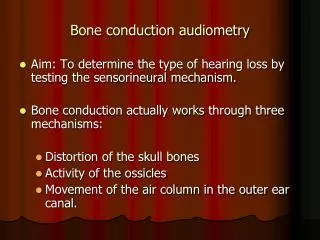
Bone-anchored hearing aid Details deleted to minimize file size. See Hearing Aids page 448 for further details. Titanium fixture Abutment Connecting screw Skin Subcutaneous tissue Bone Figure 16.6 Bone-anchored hearing aid, showing its attachment through the skin to the bone. Amended by permission from Entific Medical Systems. Source: Dillon (2001): Hearing Aids