Download
1 / 38
380 likes | 512 Views
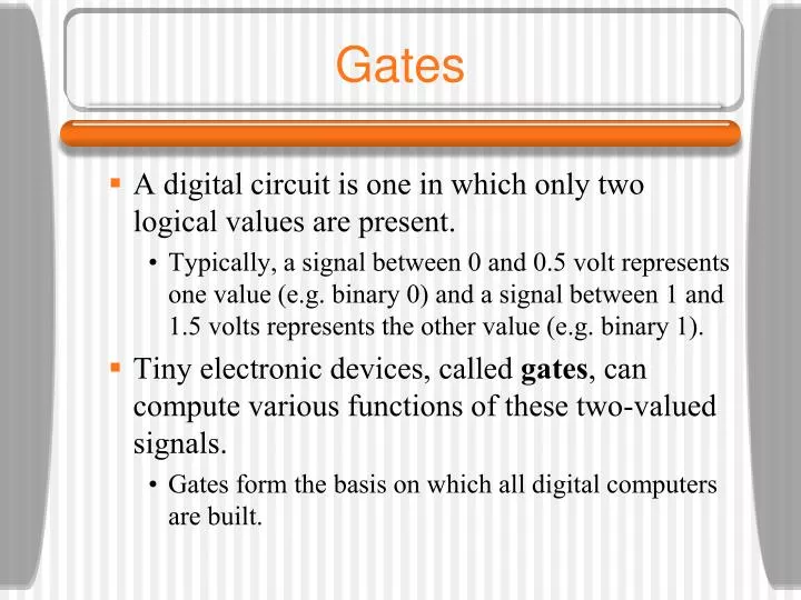
Gates. A digital circuit is one in which only two logical values are present. Typically, a signal between 0 and 0.5 volt represents one value (e.g. binary 0) and a signal between 1 and 1.5 volts represents the other value (e.g. binary 1).

E N D
Gates • A digital circuit is one in which only two logical values are present. • Typically, a signal between 0 and 0.5 volt represents one value (e.g. binary 0) and a signal between 1 and 1.5 volts represents the other value (e.g. binary 1). • Tiny electronic devices, called gates, can compute various functions of these two-valued signals. • Gates form the basis on which all digital computers are built.
Gates • A transistor can be made to operate as a very fast binary switch. • The next slide shows a bipolar transistor (the circle) embedded in a simple circuit. The transistor has three connections to the outside: • the collector • the base • the emitter • When the Vin is below a certain critical value, the transistor turns off and acts like an infinite resistance. This causes Vout to to take on a value close to Vcc.
Gates • When Vin exceeds the critical value, the transistor switches on and acts like a wire, causing Vout to be pulled down to 0 volts. • This circuit is an inverter, converting a logical 0 to a logical 1, and vice versa. The resistor is needed to limit the amount of current drawn by the transistor. • In the next figure, if both inputs are high, the output will be low. If either output is low, the output will be high. • In the third figure, the transistors are wired in parallel rather than series. If either input is high, the transistor will turn on and pull the output down.
Gates • These three circuits form the three simplest gates: • NOT gates • NAND gates • NOR gates • NOT gates are also called inverters. • If we now adopt the convention that “high” is a logical 1, and that “low” (ground) is a logical 0, we can express the output values as a function of the input values.
Gates • If the output of the NAND gate is fed into an inverter circuit, we get another circuit with precisely the inverse of the NAND gate - an AND gate. • The NOR gate can be connected to an inverter to yield an OR gate. The small circles used as part of the symbols for the inverter etc. are called inversion bubbles. • The five gates described are the principal building blocks of the digital logic level.
Gates • NAND and NOR gates require two transistors each, while the AND and OR gates require three transistors each. Therefore, many computers are based on NAND and NOR gates rather than AND and OR. • The two major technologies for constructing gates are bipolar and MOS (Metal Oxide Semiconductor). The major bipolar types are TTL (Transistor-Transistor Logic) and ECL (Emitter-Coupled Logic). MOS gates are slower than TTL and ECL but require less power and space. Most modern CPUs and memories use CMOS technology which runs on +1.5 volts.
Boolean Algebra • Boolean Algebra can be used to describe the circuits that can be built by combining gates. • A Boolean function has one or more input variables and yields a result that depends only those variables. • Define a function f such that f(A) is 1 if A is 0 and f(A) is 0 if A is 1. This function is the NOT function. • Since a Boolean function of n variables has only 2n possible combinations of inputs, the function can be completely described by giving a truth table with 2n rows of inputs/output.
Boolean Algebra • Although any Boolean function can be specified by giving its truth table, this notation becomes cumbersome as the number of variables increases. • Another notation is based on the fact that any Boolean function can be specified by telling which combinations of input variables give an output value of 1. • An apostrophe after an input variable means that its value is inverted. The absence of an apostrophe means that it is not inverted.
Boolean Algebra • Implied multiplication (or a dot) means the Boolean AND function and + means the Boolean OR function. • Example: AB’C takes the value 1 only when A = 1, B = 0 , and C = 1. • The previous truth table can be written as M = A’BC + AB’C + ABC’ + ABC as a compact way of giving the truth table. • A function of n variables can be described by giving a “sum” of at most 2nn-variable “product” terms.
Boolean Algebra • The formulation of a Boolean function as a sum of up to 2n products leads directly to a possible implementation as shown. • We can implement a circuit for any Boolean function by: • Writing down the truth table for the function • Providing inverters to generate the complement of each input • Drawing an AND gate for each term with a 1 in the result column • Wiring the AND gates to the appropriate inputs • Feeding the output of all the AND gates into an OR gate
Boolean Algebra • It is often convenient to implement circuits using only a single gate type. • It is straightforward to convert circuits generated by the previous algorithm to pure NAND or pure NOR form - all we need is a way to implement NOT, AND, and OR using a single gate type. • Both NAND and NOR gates are said to be complete, because any Boolean function can be computed using either of them.
Boolean Algebra • No other gate has this property. • Follow the previous algorithm then replace the multi-input gates with equivalent circuits using two-input gates. Replace the NOT, AND, and OR gates with the circuits of the following slide.
Circuit Equivalence • Circuit designers try to reduce the number of gates to reduce cost, space, power consumption, etc. • To reduce the complexity, a circuit with fewer gates which computes the same function must be found. Boolean algebra can be a valuable tool. • Many rules of ordinary algebra hold for Boolean algebra. AB + AC can be factored into A(B + C) using the distributive law.
Circuit Equivalence • In general, a designer starts with a Boolean function and then applies the laws of Boolean algebra to find a simpler but equivalent one. From the final function, a circuit can be constructed. • Some of the major identifies from Boolean algebra are shown in the following slide. Note that each law has two forms that are duals of each other. By interchanging AND and OR and also 0 and 1, either form can be produced from the other one.
DeMorgan’s Law • DeMorgan’s law can be extended to more than two variables, for example, (ABC)’ = A’ + B’ + C’. • DeMorgan’s law suggests an alternative notation. The following slide shows AND form with negation indicated by inversion bubbles, for both input and output. Thus an OR gate is equivalent to a NAND gate. • A NOR gate can be drawn as an AND gate with inverted inputs.
DeMorgan’s Law • Using the identities of the previous slide and the analogous ones for multi-input gates, it is easy to convert the sum-of-products representation of a truth table to pure NAND or pure NOR form. • The lines connecting the output of the AND gates to the input of the OR gates should be redrawn with two inversion bubbles. • The OR gate can then be replaced with the equivalent NAND gate.
Circuit Equivalence • The same physical gate can compute different functions, depending on the conventions used. • The following slide shows the output of a certain gate F, for different input combinations. • Both inputs and outputs are shown in volts. • If we adopt the convention that 0 volts is logical 0 and 1.5 volts is logical 1, called positive logic, we have one result. If, however, we adopt negative logic, which has 0 volts as logical 1 and 1.5 volts as logical 0, we get another function, the OR function. Usually, we will assume positive logic.
Integrated Circuits • Gates are not manufactured or sold individually, but rather in units called Integrated Circuits, often called ICs or chips. • An IC is a square piece of silicon on which some gates have been deposited. Small ICs are usually mounted in rectangular plastic or ceramic packages which can be larger than the die (2 x 2mm up to 18 x 18mm). • Along the long edges are two parallel rows of pins that can be inserted into sockets or soldered to printed circuit boards.
Integrated Circuits • The packages with two rows of pins outside and ICs inside are technically known as Dual Inline Packages or DIPs, but everyone calls them chips. • The most common packages have 14, 16, 18, 20, 22, 24, 28, 40, 64, or 68 pins. For large chips, square packages with pins on all four sides are often used. • Chips can be divided into rough classes based on the number of gates they contain:
Integrated Circuits • SSI (Small Scale Integration) circuit: 1 to 10 gates. • MSI (Medium Scale Integration) circuit: 10 to 100 gates. • LSI (Large Scale Integration) circuit: 100 to 100,000 gates. • VLSI (Very Large Scale Integration) circuit: >100,000 gates. • An SSI chip typically contains two to six independent gates, each of which can be used independently. The package generally has a notch near pin 1 to identify the orientation.
Integrated Circuits • Common types of integrated-circuit packages, including a dual-inline package (a), pin grid array (b),and land grid array (c).
Integrated Circuits • Many chips like this are available for a few cents each. In the 1970s, computers were constructed out of a large number of these chips. Today multiple CPUs and cache memory are etched onto a single chip. • We can consider all gates to be ideal so that output appears as soon as input is applied. In reality chips have a finite gate delay which includes signal propagation time and switching time. Typical delays are 100 picoseconds to 10nsec.
Combinatorial Circuits • Many applications of digital logic require a circuit with multiple inputs and multiple outputs in which the outputs are uniquely determined by the current inputs. Such a circuit is called a combinatorial circuit. • Not all circuits have this property (e.g. memory elements). A circuit implementing a truth table is a typical example of a combinatorial circuit.
Multiplexers • A multiplexer is a circuit with 2n data inputs, one data output and n control inputs that select one of the data inputs. • A multiplexer can be also be used to implement the majority function shown previously. For each combination of A, B, and C, one of the data input lines is selected. Each input is wired to either Vcc (logical 1) or ground (logical 0). • Input Di is the same as the value in row i of the truth table. • A demultiplexer routes its single input signal to one of 2n outputs, depending on the values of the control lines.
Multiplexers • An eight-input multiplexer circuit.
Decoders • A decoder takes an n-bit number as input and uses it to select (i.e. set to 1) exactly one of the 2n output lines. • A decoder can be used, for example, to select 1 of 8 memory chips given the high-order 3 bits of the address if the chips are organized so that chip 0 has addresses 0 to 256 MB, chip 1 has addresses 256 MB to 512 MB, and so on.