Download

1 / 19
400 likes | 1.07k Views
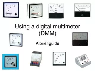
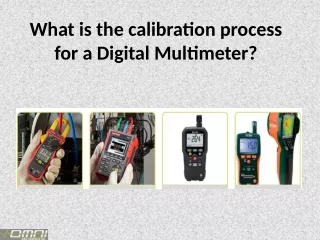
Digital Multimeter. Multimeters are designed and mass produced. The simplest and cheapest types may include features which are not likely to use. Digital meters give an output in numbers, usually on a liquid crystal display. Switched. Autoranging. What do meters measure?.

E N D
Multimeters are designed and mass produced. The simplest and cheapest types may include features which are not likely to use. Digital meters give an output in numbers, usually on a liquid crystal display.
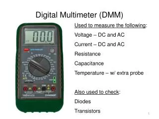
What do meters measure? • A meter is a measuring instrument. An ammeter measures current, a voltmeter measures the potential difference (voltage) between two points, and an ohmmeter measures resistance. A multimeter combines these functions, and possibly some additional ones as well, into a single instrument.
Multimeter as a Ammeter • Turn Power Off before connecting multimeter • Break Circuit • Place multimeter in series with circuit • Select highest current setting, turn power on, and work your way down. • Turn power off • Disconnect multimeter. • Reconnect Circuit
Ammeter mode measures current in Amperes. To measure current you need to power off the circuit, you need to break the circuit so that the ammeter can be connected in series. All the current flowing in the circuit must pass through the ammeter. Meters are not supposed to alter the behavior of the circuit, so the ammeter must have a very LOW resistance. The diagrams below show the connection of a multimeter to measure current.
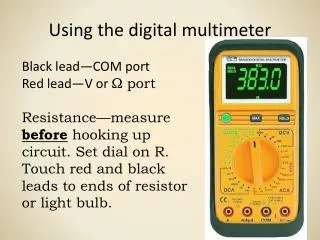
Multimeter as a Voltmeter To use a multimeter as a voltmeter it is connected in parallel between the two points where the measurement is to be made. The voltmeter provides a parallel pathway so it needs to be of a high resistance to allow as little current flow through it as possible. Voltage measurements are the most common measurements. Processing of electronic signals is usually thought of in voltage terms. Voltage messurements are easy to do because you do not need to change the original circuit you only need to touch the points of interest.
Mutimeter as a Voltmeter • Select the DC or AC Volts • If not a auto-ranging mutimeter then start at the highest volts scale and work your way down. • Be very careful to not touch any other electronic components within the equipment and do not touch the metal tips.
Multimeter as a Ohmmeter • Power always has to be off • Component has to be removed from circuit • Start at lowest Ohm setting
Review • A meter capable of checking for voltage, current, and resistance is called a multimeter, • As voltage is always relative between two points, a voltage-measuring meter ("voltmeter") must be connected to two points in a circuit in order to obtain a good reading. Be careful not to touch the bare probe tips together while measuring voltage, as this will create a short-circuit! • Remember to always check for both AC and DC voltage when using a multimeter to check for the presence of hazardous voltage on a circuit. Make sure you check for voltage between all pair-combinations of conductors, including between the individual conductors and ground!
Review • When in the voltage-measuring ("voltmeter") mode, multimeters have very high resistance between their leads. • Never try to read resistance or continuity with a multimeter on a circuit that is energized. • Current measuring meters ("ammeters") are always connected in a circuit so the electrons have to flow through the meter. • When in the current-measuring ("ammeter") mode, multimeters have practically no resistance between their leads. This is intended to allow electrons to flow through the meter with the least possible difficulty. If this were not the case, the meter would add extra resistance in the circuit, thereby affecting the current.