Download
1 / 23
230 likes | 238 Views
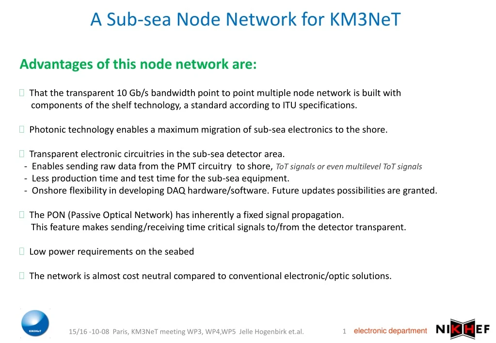
A Sub-sea Node Network for KM3NeT. Advantages of this node network are: That the transparent 10 Gb/s bandwidth point to point multiple node network is built with components of the shelf technology, a standard according to ITU specifications.

E N D
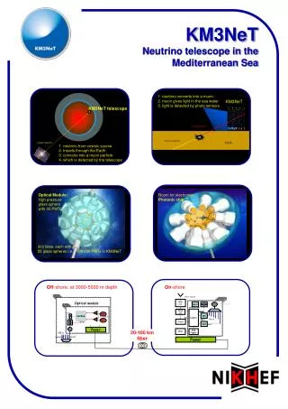
A Sub-sea Node Network for KM3NeT • Advantages of this node network are: • That the transparent 10 Gb/s bandwidth point to point multiple node network is built with components of the shelf technology, a standard according to ITU specifications. • Photonic technology enables a maximum migration of sub-sea electronics to the shore. • Transparent electronic circuitries in the sub-sea detector area. - Enables sending raw data from the PMT circuitry to shore, ToT signals or even multilevel ToT signals-Less production time and test time for the sub-sea equipment. - Onshore flexibility in developing DAQ hardware/software. Future updates possibilities are granted. • The PON (Passive Optical Network) has inherently a fixed signal propagation. This feature makes sending/receiving time critical signals to/from the detector transparent. • Low power requirements on the seabed • The network is almost cost neutral compared to conventional electronic/optic solutions. 15/16 -10-08 Paris, KM3NeT meeting WP3, WP4,WP5 Jelle Hogenbirk et.al.
History of development • Innovative design study using photonic technology for data transport started after the VLVnT workshop in Amsterdam, 2003 • Various studies on conceptual aspects of a novel architecture by Nikhef, 2003-2005 • Photonic workshop at Nikhef within the framework of WP4, November 2006 • First basic experiments at the University of Eindhoven, summer 2007 • Feasibility study results presented by CIP at the KM3NeT CDR workshop, November 2007 • Realization with industry (CIP)of ‘SPARK’ with 3 optical channels 10 Gb/s, August 2008 15/16 -10-08 Paris, KM3NeT meeting WP3, WP4,WP5 Jelle Hogenbirk et.al.
Architecture of KM3NeT Node Network • Dense Wavelength Division Multiplexing • Array of centralized continuous wave laser sources on-shore, shared by all Optical Modules • Optical power splitting and amplification • ~ 100 wavelengths per fiber • ~ 100 fibers • for 10.000 OM’s • A single fiber working between Optical Module and Junction Box • Separate go/return fibers to shore due to Coherent Rayleigh backscatter • Accurate timing over fiber is proved • PMT data taking/multiplexing • Initially electric, but on longer term “all Optical” frontend solutions feasible. 15/16 -10-08 Paris, KM3NeT meeting WP3, WP4,WP5 Jelle Hogenbirk et.al.
Definition of an optical channel An optical channel is l1 l1 DWDM DWDM ln ln • A per wavelength transparent point to point connection over fiber • 1 fiber can carry more than 100 wavelengths • An individual optical channel can have a bandwidth from DC to over 40 Gb/s (we use an ITU standard of 10Gb/s) • An optical channel can be applied bidirectional over the same fiber DWDM (Dense Wavelength Division Multiplexing) AWG (Arrayed Wave Guide) Similar components 15/16 -10-08 Paris, KM3NeT meeting WP3, WP4,WP5 Jelle Hogenbirk et.al.
Use of an optical channel An optical channel is also bidirectional (And has a rigid propagation time !!) l1 l1 DWDM DWDM ln CW ln modulated ln REAM ln CW laser Serial data to be transported Receiver (PIN) Serial data received 15/16 -10-08 Paris, KM3NeT meeting WP3, WP4,WP5 Jelle Hogenbirk et.al.
Arrayed Waveguide Grating An AWG can be used as a wavelength router… PIN clock/data on l1 AWG CW l1 l2 l3 l4 l1 l2 l3 l4 clock/data PIN l1 l2 l3 l4 l1 l2 l3 gate REAM CW l1 l2 l3 l4 OM data To OMs not used lN+1 lN clock/data CIP Confidential 6 15/16 -10-08 Paris, KM3NeT meeting WP3, WP4,WP5 Jelle Hogenbirk et.al.
Schematic View of the Node Network DWDM Mux Presentation on CDR workshop November 2007 100km fibre path l1 Single fibre feed shared for feed wavelength comb cw DWDM lasers (up to 100 wavelengths) Comms & Timing 1 of 100 return fibres Power splitters to feed up to 100 units Up to 100 reflective modulators Data out 2km Optical Amplifiers PMTs Data Receiver WDM Demux l1 DWDM Demux Shore Station OMs Optical receiver Proposed Architecture for Km3NeT to Avoid Rayleigh Back Scatter Limitation Electrical drive to modulator. (single modulator gates all DWDM Wavelengths) Undersea Station 15/16 -10-08 Paris, KM3NeT meeting WP3, WP4,WP5 Jelle Hogenbirk et.al.
Transmission Timing Skew • Wavelength dependent timing skew due to group delay over 100km (LEAFâ) • ~90ns for 25GHz comb (1530nm – 1550nm) • ~140ns for 40GHz comb (1530nm – 1562nm) • This is deterministic, at fixed temperature • Temperature dependence • estimates based on published data… • Bulk: 96ps/oC per km 9.6ns/oC (100km) (LEAFâ) • Skew: lo ~ 0.03nm/oC 8.6ps/oC (100km) (standard fibre 40GHz comb) • Shows that relative timing information will stay constant, absolute timing varies insignificant with temperature. 15/16 -10-08 Paris, KM3NeT meeting WP3, WP4,WP5 Jelle Hogenbirk et.al.
Clock and Timing Calibration • Shore based master clock / framing generator • Distribute clock sync and framing to each Optical Module by over-modulating cyclic copy of DWDM seed using distribution property of dual input AWG • each OM receives two wavelengths, one cw for return data modulation,one conveying clock and data (not returned to shore) • Use pulse echo measurements to calculate relative delay of each OM 15/16 -10-08 Paris, KM3NeT meeting WP3, WP4,WP5 Jelle Hogenbirk et.al.
Example of Signal Propagation 100km 2km A cw seed Y AWG OM Gated amplifier Loop timing pulse M 100km 100 return fibres A’ Optical Module Junction Box X Shore Station TX-Y = TY-X For illustration (or measured during construction) TA’-OM-A’ Pulse echo A’ to all OMs and M TOM-A’ = (TA’-OM-A’)/2 TA-OM-A’ clock / framing round trip measured TA-OM = TA-OM-A’ - TOM-A’ 15/16 -10-08 Paris, KM3NeT meeting WP3, WP4,WP5 Jelle Hogenbirk et.al.
SPARK Sophisticated Photonic Architecture Reference for KM3NeT Joint activity of Nikhef and CIP Purchased by Nikhef • Required: • A reference photonic test bench based on a KM3NeT architecture for a node network • with10Gb/s bandwidth/OC, with an intrinsic signal propagation time jitter of << 50 ps. • What we have: • A reference photonic test bench based on a KM3NeT architecture for a node network • with10Gb/s bandwidth/OC, with an intrinsic signal propagation ime jitter of << 50 ps. • The door is wide open for: • Optimizing PON components for a final node network to be deployed. • Transparently connects front-end (sub-sea) electronics to backend (on-shore) electronics with signal propagation time only. • The entire test bed is relatively easy to copy: all parts are COTS(Components Of The Shelf) • A low cost test bed with reduced components for a single optical channel can be very helpful for developing front-end and back-end electronics in different laboratories. 15/16 -10-08 Paris, KM3NeT meeting WP3, WP4,WP5 Jelle Hogenbirk et.al.
Outline of SPARK Temperature control Temperature control cw DWDM lasers (2 wavelengths) Mux Tuneable laser input Temperature control & Laser Bias Spare for loop timing Reflective modulators £2km DWDM 10G Data Receivers 10G Drivers 100km LEAF SOA Line Amplifier If 100 km and10Gb/s Pre Amplifier not fitted DWDM Undersea Station Shore Station 15/16 -10-08 Paris, KM3NeT meeting WP3, WP4,WP5 Jelle Hogenbirk et.al.
SPARK in reality 10 km Leaf fiber Shore station Sub-sea station 15/16 -10-08 Paris, KM3NeT meeting WP3, WP4,WP5 Jelle Hogenbirk et.al.
Bi-directional DWDM for 20 channels 15/16 -10-08 Paris, KM3NeT meeting WP3, WP4,WP5 Jelle Hogenbirk et.al.
The REAM in the off-shore application From front-end electronics to fiber takes 2 components in OM REAM driver Clock input Reflective Electro Absorption Modulator Data input (next stage the REAM driver will reside in the REAM housing) 15/16 -10-08 Paris, KM3NeT meeting WP3, WP4,WP5 Jelle Hogenbirk et.al.
SPARK Shore Station 15/16 -10-08 Paris, KM3NeT meeting WP3, WP4,WP5 Jelle Hogenbirk et.al.
SPARK First Measurements Laser & AWG Spectrum 15/16 -10-08 Paris, KM3NeT meeting WP3, WP4,WP5 Jelle Hogenbirk et.al.
10Gb/s eye pattern at CIP 10 Gb/s eye pattern BER no errors 15/16 -10-08 Paris, KM3NeT meeting WP3, WP4,WP5 Jelle Hogenbirk et.al.
Other DAQ News from Nikhef Transfer exact timing by using a coded data communication channel Xilinx Virtex-5 ML507 Evaluation Kit Start Stop Rx 8B/10B Encoded Tx 8B/10B Encoded 15/16 -10-08 Paris, KM3NeT meeting WP3, WP4,WP5 Peter Jansweijer et.al.
A KM3NeT timing proposal Broadcast l1 JB l2 l3 - l27 OM One Reference Clock (GPS) PMTs Local Clocks are phase locked; thus isochronous. But their values have an offset l1 + l27 Loop timing Loop timing OM l1 PMTs l2 + l1 Data Receiver l3 + l2 Mod l4 + l5 l27 + l26 Individual Optical Channel DU Shore Station Undersea Station CIP Confidential 15/16 -10-08 Paris, KM3NeT meeting WP3, WP4,WP5 Peter Jansweijer et.al.
+ 320 ps 0111010110000010101101110101100000101011011101011000001 0 0111010110000010101101110101100000101011011101011000001 0111010110000010101101110101100000101011011101011000001 19 19 Timing over 8B10B data channel Tx 8B/10B Encoded K28.5 D16.2 K23.7 K23.7 K28.5 D16.2 K28.5 D16.2 K28.5 D16.2 K28.5 D16.2 K28.5 D16.2 IDLE CharExt IDLE IDLE IDLE IDLE IDLE Start Stop Rx 8B/10B Encoded K28.5 D16.2 K28.5 D16.2 K28.5 D16.2 K28.5 D16.2 K23.7 K23.7 K28.5 D16.2 K28.5 D16.2 IDLE IDLE IDLE IDLE CharExt IDLE IDLE Variable propagation delay RxRecClk Reset (= resynchronize & Byte Re-Align) BitSlide(4:0) 6.4 ns At 3.125 Gbps: Absolute timing is determined by “Start/Stop” delay (in 20 bit steps of 6.4 ns) plus BitSlide fine delay (20 steps of 320 ps) 0 0000 = 0 1 0011 = 19 15/16 -10-08 Paris, KM3NeT meeting WP3, WP4,WP5 Peter Jansweijer et.al.
For the skeptic…Does this work from board to board? Yes it does! Coarse time (6.4 ns Steps) 3.125 Gbps via Constant Impedance Trombone Line Transmitter LatticeLFSCM25 Receiver XilinxVirtex-5 Receiver locked to Transmitter Oscillator Transmitter Crystal Oscillator Fine time (320 ps Steps) 15/16 -10-08 Paris, KM3NeT meeting WP3, WP4,WP5 Peter Jansweijer et.al.
To be continued 15/16 -10-08 Paris, KM3NeT meeting WP3, WP4,WP5 Jelle Hogenbirk et.al.