Download
1 / 14
140 likes | 283 Views
Electronics and DAQ Summary. M. V. Purohit for Jing Wei Zhao, Zepu Mao, Huayi Sheng, Ping Ping Zhao, Shudi Gu, Yong Zhao Zhou et al. Vertex Chamber. This device is small and will be considered later – after the workshop. Q to T based mainamp. Cern HPTDC based TDC. Preamp. Wire

E N D
Electronics and DAQ Summary M. V. Purohit for Jing Wei Zhao, Zepu Mao, Huayi Sheng, Ping Ping Zhao, Shudi Gu, Yong Zhao Zhou et al.
Vertex Chamber This device is small and will be considered later – after the workshop.
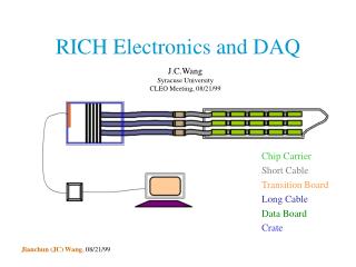
Q to T based mainamp Cern HPTDC based TDC Preamp. Wire signal VMEbus trigger Calibration Online MDC: Choice of Design Schemes Scheme 1: Based on《Q to T converter + HPTDC》
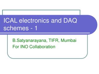
Trigger Q measurement Preamp dE/dx Wire Signal Mainamp timing T measurement Vth Trigger VMEbus Clock Calibration online MDCScheme 2: Based on FADC and HPTDC.
MDC Issues • Decision needed on Scheme 1 vs 2 • Rests partly on available budget per channel • Many noise issues: • Reflection from ends of cables • Channels closer to beam: no room for preamps on end-plates • Cross-talk; Low noise supplies
FromL1Trigger Splitter Pre-amp PMT Signal Driver ADC Read-out 10ns LL L-threshold Delay Stop TAC + FADC Read-out L0 trigger Start H_threshold HL To Trigger From Online Calibration TOF Electronics BlockDiagramoftheTOFelectronics
Barrel electromagnetic Calorimeter Electronics Preamplifiers Post amplifier B G O Charge measurement ∑ CR controller (RC)2 Σ V M E Trigger ∑ Fan - out L1 Trigger C Trigger CL1 calibration L1 Trigger System block diagram
EMC issue • Major issue is noise reduction • Cost is not a serious problem here
Muon Chambers • Number of channels needs to be determined from physics considerations
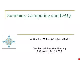
DAQ BESIII’s sub-detectors are: • Vertex Chamber • Main Drift Chamber • TOF plus CCT Counter • Electromagnetic Calorimeter • MUON Identifier Electronics will consist of five sub-systems correspondingly. Total channel amount is about 50K~77K.
DAQ Schedule • Software people exist. It is assumed that sufficient number of students will be found as necessary. • Testing of DAQ subsystems must be possible before completion of FEE subsystems. Will help with specifications. • This must include diagnostics.
Schematic of BES III Trigger VC DISC Hit Count L0 trigger Logic FEE L0P TOF DISC Hit/Seg Count Global Trigger Logic MDC DISC Track Seg. Finder Track Finder DAQ EMC BTE Sum Tile Sum Tile Processor Total Ener Sum L1P MU DISC Mu track CLOCK RF TTC 2.4 s
Trigger Issue • Can L0 be used for timing instead of L1? • Should segmentation of of cells match MDC? Might make life simpler. • Interface personnel need to be designated.
System-wide issues • Manpower: perhaps sufficient, but experienced people (engineers!) needed. Visits from foreign experts? • Detailed schedules need to be drawn up: 1.5 to 2 years estimate from most groups needs timelines. Interface with other groups. Fallback options.