Download
1 / 46
520 likes | 865 Views
Introduction to Capacitors. Chapter 20. Capacitance Vocab. Capacitance – the property of a dielectric to store electric charge. Dielectric – an insulator used to store electric charge in a capacitor Electrode - A collector or emitter of electric charge (not necessarily metallic)

E N D
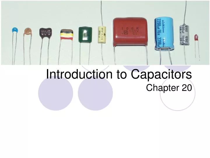
Introduction to Capacitors Chapter 20
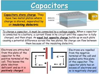
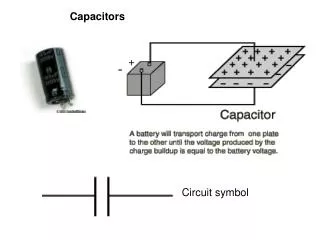
Capacitance Vocab. • Capacitance – the property of a dielectric to store electric charge. • Dielectric – an insulator used to store electric charge in a capacitor • Electrode - A collector or emitter of electric charge (not necessarily metallic) • A capacitor is made up of 2 electrodes and a dielectric. • Permittivity - how well a dielectric material can establish electrostatic lines of force. (Like permeability but for capacitors)
Inside a capacitor Electrodes or
Top 8 Capacitor Concepts • Do not use the property of magnetism like inductors do! • Capacitors store energy in an electrostatic field instead • The number of electrons it can store in this field determines its capacitance size • The units of Capacitance are measured in Farads [F] and the symbol for Capacitance is C. • Capacitors act like springs • Opposes DC but passes high frequency AC • Easy to flow during change but is open when DC • Some capacitors are polarity sensitive (For DC circuits) Signal to ground • Current doesn’t actually flow through a capacitor, rather it accumulates charge.
In the presence of an electric field, electrons are attracted towards the more positive side.
Factors affecting size of capacitance • Laser analogy • Looking at the capacitor on the left, which facts do you think affect the size of the capacitor? • Area of the plates • Distance between the plates • Dielectric constant – the material the dielectric is made of.
The equation given for capacitance size: K = Dielectric Constant (or Permittivity) From Table 20.1 A = Area of plate (measured in meters2) D = Distance between plates (measured in meters) Everything is referenced to vacuum as K = 1, because a vacuum is a very weak dielectric
Determining Capacitance Size Dielectric Material - Air A = .004m2 D = .001m Find the size of the Capacitance given the above info.
Another example Dielectric Material – Aluminum Oxide A = 4cm x 6cm D = .0005m Find the size of the Capacitance given the above info.
Another example Dielectric Material – Tantalum Oxide A = 3cm x 3cm D = 4um Find the size of the Capacitance given the above info.
The typical range for a capacitor is from .5F to 1 pF. More generally for our class, between 1mF and 10nF
RVOTD http://www.youtube.com/watch?v=EjOvI0TOx98&NR=1
All these examples beg the question:What is a Farad? For any given capacitor, the ratio of the charge on one plate to the potential difference across the plates is a constant. This constant is the property called capacitance. A capacitor has a capacitance of 1 Farad if 1 Coulomb of charge must be deposited to raise the potential difference by 1V across the capacitor. 1 Farad = 1 coulomb/1 volt
Determining capacitance Determine the capacitance when 50uC of charge deposited on the plates raises the potential difference by 2V. Determine the Charge required to raise a 10nF capacitor by 15V.
So how does current, voltage and capacitance relate? If you recall, what does Current equal in terms of Charge? A constant current of 5mA charges a 20uF capacitor in 80ms. What is the voltage across the capacitor?
… but t is always a change in time, not just a particular instant. It’s also a change in charge Q, which causes there to be a change in voltage. (See 20.1.5) This equation should look very similar to one we’ve already worked with.
Determine the capacitor current when the voltage across a 4uF capacitor changes from 16V to 24V in 2ms.
Another Example Determine the capacitor current when the voltage across a 100nF capacitor changes from 0V to 5V in 2us.
Read page 143 on your own. The starting up of voltage across a capacitor is similar to the starting up of current across an inductor. The starting up of current across a capacitor is similar to the starting up of voltage across an inductor.
There are many types of capacitors, each one useful for different applications.
Mica Capacitor (See table 155 for typical applications and pro’s/con’s) Notice the Voltage Rating. Is this capacitor polar sensitive?
Aluminum Oxide Capacitor When installing this type of capacitor, you must put the side with the negative dashes on the most negative side of the circuit. This is an Electrolytic Capacitor which means it is polar sensitive. This kind is typically used in DC circuits since AC circuits are not polarized.
Capacitor Codes What do all the letters and numbers mean on a capacitor? They symbols on a capacitor refer to both the capacitance size and the temperature affect on the capacitance size. The capacitors in your kit have a tolerance of +/-20% How do you determine the size of a capacitor? Determining capacitance size in some cases is not as straight forward as determining resistance size.
There are 3 classes of capacitors – Class I, II, and III • Class I dielectrics display the most stable characteristics. • The most common Class I dielectric is the COG designation, which is 0ppm/°C ±30ppm/°C, which is equivalent to the NPO (zero temperature coefficients) code defined by MIL specifications
Table 20.4; Temperature Coefficient of Class I Dielectrics Determine the temp. coefficient of a capacitance with the marking R2G. -220 ppm/ºC ±30ppm/ºC
Class I dielectrics display the most stable characteristics. • The most common Class I dielectric is the COG designation, which is 0ppm/°C ±30ppm/°C, which is equivalent to the NPO (zero temperature coefficients) code defined by MIL specifications • Skip the next 3 slides
Code Practice! • Using the chart in section 20.4.1, table 20.4 determine the temperature coefficient of a ceramic capacitor marked with the following: • U4M, P6G, T0G, R7K • -75000ppm/°C ±1000ppm/°C • 15ppm/°C ±30ppm/°C • -47ppm/°C ±30ppm/°C • 220ppm/°C ±250ppm/°C
Class II • Offer much higher constants than Class I, but with less stable properties to changes in temperature, and voltage. • They have a maximum capacitance change of ±15% or less over an operating temperature range of -55°C to +125°C. • They are called general-purpose capacitors.
Table 20.5 Max Change in Capacitance • Determine: • Y5V • X7R • Y5V= +22%, -82% maximum change from +25°C, over a -30°C to +85°C temperature range.
Capacitance Size – Through Hole If the capacitor is physically large enough, it will say the capacitor size right on it. Otherwise, whole number values on capacitors usually indicate a value in picofarads. Ie: 102 = 1 0 with 2 more 0’s. So 1000 picofarads or 1nF. See table 20.6 for value interpretations What is the value and tolerance of a cap that says 223J? 22nF+/-5% = .022uF What is the value and tolerance of a cap that says 334K? 330nF +/-10% = .330uF What is the value of a cap that says 229? 2.2pF
Capacitance Size – Through Hole If the value is 4 numbers long, then just read it directly in pF
Capacitance Size – Surface Mount Capacitance is always given in picoFarads The first digit is typically a letter. This letter represents a number. (See table 20.7) ie: U = 5.6 The second digit is the multiplier Ex: What capacitance is T2? T = 5.1 & 2 = x100…… So 5.1x100 = 510pF What capacitance is X4? 75000pF = 75nF = 0.075uF What capacitance is 39? 39pF (If there is no letter, the number is read directly in pF.)
How to add capacitors in parallel and in series. So why is this true? What is the reasoning behind this?
What is Stray Capacitance? Stray capacitance is more noticeable at higher frequencies Ways to reduce stray capacitance 1. Use low frequencies (not really an option) 2. Keep lead lengths short 3. Use lots of space between wires and traces 4. Mount components high off chassis
What would happen if you measured resistance of a capacitor using a VOM? How to could you tell if a cap is shorted? How to could you tell if a cap has an open?
Finish going over Capacitor/Inductor Comparison Handout Go over Cap/Ind Lead Lag handout