Download
1 / 31
310 likes | 433 Views
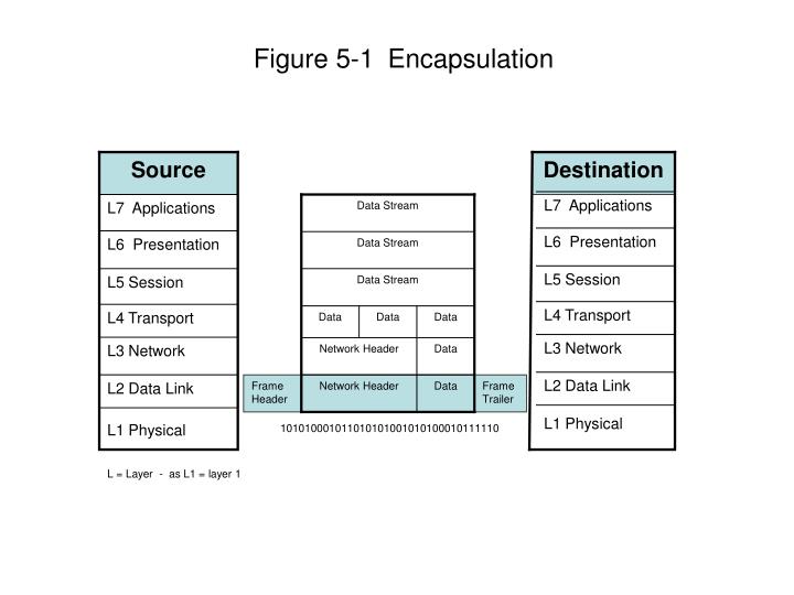
Source. Destination. L7 Applications. L7 Applications. Data Stream. L6 Presentation. L6 Presentation. Data Stream. L5 Session. L5 Session. Data Stream. L4 Transport. L4 Transport. Data. Data. Data. L3 Network. L3 Network. Network Header. Data. L2 Data Link. L2 Data Link.

E N D
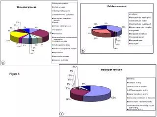
Source Destination L7 Applications L7 Applications Data Stream L6 Presentation L6 Presentation Data Stream L5 Session L5 Session Data Stream L4 Transport L4 Transport Data Data Data L3 Network L3 Network Network Header Data L2 Data Link L2 Data Link Network Header Data Frame Header Frame Trailer L1 Physical L1 Physical 101010001011010101001010100010111110 L = Layer - as L1 = layer 1 Figure 5-1Encapsulation
Email being Composed Email Data Stream Data Layer 5 Data Data Data Segment Layer 4 Network Header Data Layer 3 Packet Frame Header Network Header Data Frame Trailer Layer 2 Frame Bits Layer 1 1010100010111101010101001010100010111110 Figure 5-2Data Encapsulation Process
TCP/IP Model OSI Model Layer 7 Application Application Layer 6 Presentation Layer 5 Session Layer 4 Transport Transport Layer 3 Network Network Layer 2 Data Link Link Layer 1 Physical Figure 5-3 OSI and TCP/IP models compared
Server Client Figure 5-5 An example of a client/cerver network
Server Controller Workstation Figure 6 - Star Topology
Computer Server Printer workstation Figure 5-7 A Bus Topology
Server Workstation Figure 8- Ring Topology
Clear to send A A A A Sending Wait random time collision Clear to send Sending B B B B 1 2 3 4 Figure 5-9 A CSMA/CD collision
or Collision Domain 1 Collision Domain 2 or Router Switch Bridge Figure 5-10 Collision Domain
RJ45 Active Hub Figure 5-11 Modular Jack and Active Hub
2 Mbps 10 Mbps 2 Mbps 2 Mbps 2 Mbps 2 Mbps Figure 5-12 A network segment built on a 10 Mbps hub
Segment 1 A C B 01-20-0D-7C-01-9A 01-3A-2D-6C-0C-2A 01-20-2D-7C-DC-43 Bridge Segment 2 D E F 01-A2-1D-75-B1-12 01-0B-0D-7C-1F-3D 00-20-6D-7C-01-BC Figure 5-13 Bridging Two Network Segments
Ethernet Switch A 100 Mbps 100 Mbps B 100 Mbps 100 Mbps 100 Mbps 100 Mbps C D E Workstation Server Figure 5-14 An Example of a Switched Ethernet Configuration
Accounting Engineering Marketing Server Farm D Internet or WAN Figure 5-15 A VLAN environment
New York Point-to-Point CSU/DSU CSU/DSU Chicago Paris LAN CSU/DSU CSU/DSU CSU/DSU Rome CSU/DSU New York LAN LAN LAN LAN LAN LAN Multipoint CSU/DSU Chicago Paris LAN CSU/DSU CSU/DSU Rome CSU/DSU Figure 5-16 Point-to-Point and Multipoint (daisy-chained)
Computer “Z” Computer “Y” 2 6 4 1 7 3 8 Packets: A, B, C, and D Leave Computer “Y” via“1” Path Taken 5 Packet Arrives at “9” Re-Ordered and delivered to computer “Z” 9 A 1-2-3-4-6-5-7-8-9 (longest path) 4th A B 1-2-4-5-8-9 2nd B C 1-3-5-8-9 (shortest path) 1st C D 1-2-6-5-6-8-9 3rd D Figure 5-17 X.25 Pack Switched Network
A A A A A A Packet Switch B B B B B B A B B C B A C C C C C C C Time Division Multiplexing Data Flow Figure 5-18 Statistical Pack switching Virtual Circuit
Voice A A A A A A Multiplexed cell stream ATM Multiplexer Video B B B B B B A B B C B A C Data C C C C C C Data Flow Figure 5-19 Combining different services onto a single access channel
LAPD LAPD LAPD LAPD LAPD LAPD SP SP SP SP SP SP LAPD LAPD SP = Switch Point PVC = DTE or FRAD = Figure 5-22 PVCs in a Frame Relay network
Long-distance digital channel Physical interface V.35 Physical interface V.35 DDS Hub CSU/DSU DTE DTE DDS Hub CSU/DSU Data Access Lines Data Access Lines Figure 5-17 DDS Components
SDLC Host RJE Station Terminal X.25 Host Terminal Asynch Terminal PS PS PS PS PS PS PS PS PS PS = Packet Switch Figure 5-18 Pack switching