Download
1 / 31
310 likes | 314 Views
Learn about electrical oscillations, LC circuits, and alternating current in this lecture. Understand the concept of damping in an LCR circuit and its effects on oscillations. Explore the factors that can damp oscillations in an LC circuit.

E N D
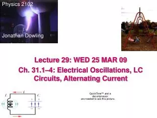
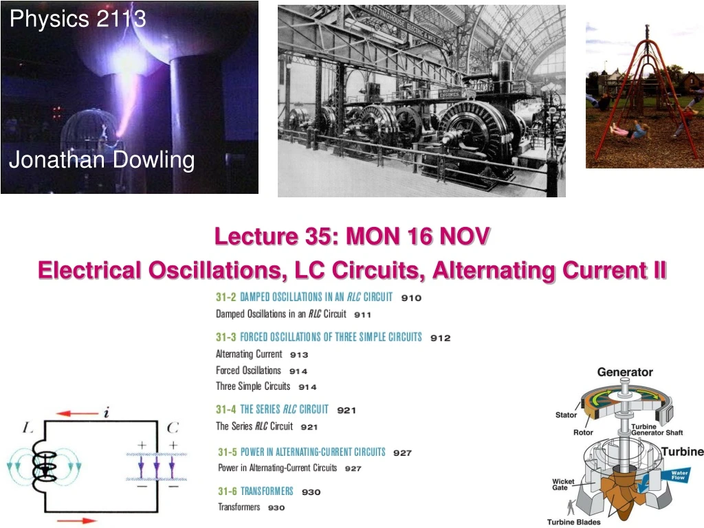
Physics 2113 Jonathan Dowling Lecture 35: MON 16 NOV Electrical Oscillations, LC Circuits, Alternating Current II
1 . 0 0 . 8 0 . 6 U E 0 . 4 0 . 2 0 . 0 0 4 8 1 2 1 6 2 0 t i m e ( s ) Damped LCR Oscillator C L R Ideal LC circuit without resistance: oscillations go on forever; ω = (LC)–1/2 Real circuit has resistance, dissipates energy: oscillations die out, or are “damped” Math is complicated! Important points: • Frequency of oscillator shifts away from ω = (LC)-1/2 • Peak CHARGE decays with time constant = • τQLCR=2L/R • For small damping, peak ENERGY decays with time constant • τULCR= L/R
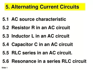
31.2.1. Which one of the following choices will damp oscillations in an LC circuit? a) increase the inductance b) increase the emf c) increase the circuit resistance d) increase the capacitance
31.2.1. Which one of the following choices will damp oscillations in an LC circuit? a) increase the inductance b) increase the emf c) increase the circuit resistance d) increase the capacitance
Q(t) t(s)
Summary • Capacitor and inductor combination produces an electrical oscillator, natural frequency of oscillator is ω=1/√LC • Total energy in circuit is conserved: switches between capacitor (electric field) and inductor (magnetic field). • If a resistor is included in the circuit, the total energy decays (is dissipated by R).
Alternating Current: To keep oscillations going we need to drive the circuit with an external emf that produces a current that goes back and forth. Notice that there are two frequencies involved: ω at which the circuit would oscillate “naturally”. The other is ωd the driving frequency at which we drive the oscillation. However, the “natural” oscillation usually dies off quickly (exponentially) with time. Therefore in the long run, circuits actually oscillate with the frequency at which they are driven. (All this is true for the gentleman trying to make the lady swing back and forth in the picture too).
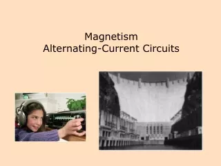
Alternating Current: We have studied that a loop of wire, spinning in a constant magnetic field will have an induced emf that oscillates with time, That is, it is an AC generator. AC’s are very easy to generate, they are also easy to amplify and decrease in voltage. This in turn makes them easy to send in distribution grids like the ones that power our homes. Because the interplay of AC and oscillating circuits can be quite complex, we will start by steps, studying how currents and voltages respond in various simple circuits to AC’s.
Example 1 : Tuning a Radio ReceiverDriven RLC With EMF Antennal FM radio stations: frequency is in MHz. The inductor and capacitor in a car radio have one program at L = 1 mH & C = 3.18 pF. Which is the FM station? WRKF 89.3 What is the wavelength Of the radio wave from The tower?
Example 1 : Tuning a Radio ReceiverDriven RLC at Resonance With EMF Antenna
31.6: Forced Oscillations: In the power grid we make sure that all circuits are far away From any resonances!
AC Driven Circuits: 1) A Resistor: For time dependent periodic situations it is useful to represent magnitudes using Steinmetz “phasors”. These are vectors that rotate at a frequency wd , their magnitude is equal to the amplitude of the quantity in question and their projection on the vertical axis represents the instantaneous value of the quantity. Charles Steinmetz Resistors behave in AC very much as in DC, current and voltage are proportional (as functions of time in the case of AC), that is, they are “in phase”.
AC Driven Circuits: 2) Capacitors: Capacitors “oppose a resistance” to AC (reactance) of frequency-dependent magnitude 1/ωd C (this idea is true only for maximum amplitudes, the instantaneous story is more complex).
AC Driven Circuits: 3) Inductors: Inductors “oppose a resistance” to AC (reactance) of frequency-dependent magnitude wd L (this idea is true only for maximum amplitudes, the instantaneous story is more complex).
Transmission lines Erms=735 kV , Irms = 500 A Home Step-down transformer Step-up transformer 110 V T2 T1 R = 220Ω Power Station Ptrans=iV = “big” Pheat=i2R = “small” Solution: Big V! (31-24)
The DC vs. AC Current Wars Thomas Edison pushed for the development of a DC power network. Nikola Tesla was instrumental in developing AC networks. George Westinghouse backed Tesla’s development of an AC power network. Edison was a brute-force experimenter, but was no mathematician. AC cannot be properly understood or exploited without a substantial understanding of mathematics and mathematical physics, which Tesla possessed.
The Tesla Three-Phase AC Transmission System The most common example is the Tesla three-phase power system used for industrial applications and for power transmission. The most obvious advantage of three phase power transmission using three wires, as compared to single phase power transmission over two wires, is that the power transmitted in the three phase system is the voltage multiplied by the current in each wire times the square root of three (approximately 1.73). The power transmitted by the single phase system is simply the voltage multiplied by the current. Thus the three phase system transmits 73% more power but uses only 50% more wire.
Niagara Falls and Steinmetz’s Turning of the Screw Against General Electric and Edison's proposal, Westinghouse, using Tesla's AC system, won the international Niagara Falls Commission contract. Tesla’s three-phase AC transmission became the World’s power-grid standard. Transforming DC power from one voltage to another was difficult and expensive due to the need for a large spinning rotary converter or motor-generator set, whereas with AC the voltage changes can be done with simple and efficient transformer coils that have no moving parts and require no maintenance. This was the key to the success of the AC system. Modern transmission grids regularly use AC voltages up to 765,000 volts.
31.11.2. The ac adapter for a laptop computer contains a transformer. The input of the adapter is the 120 volts from the ac wall outlet. The output from the transformer is 20 volts. What is the turns ratio of the transformer? a) 0.17 b) 6 c) 100 d) This cannot be determined without knowing how many turns one of the coils in the transformer has.
31.11.2. The ac adapter for a laptop computer contains a transformer. The input of the adapter is the 120 volts from the ac wall outlet. The output from the transformer is 20 volts. What is the turns ratio of the transformer? a) 0.17 b) 6 c) 100 d) This cannot be determined without knowing how many turns one of the coils in the transformer has.