Download
1 / 31
310 likes | 510 Views
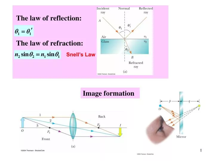
The law of reflection:. The law of refraction:. Snell’s Law. Image formation. Chapter 23. Ray Optics - Applications: Image Formation. Images are always located by extending diverging rays back to a point at which they intersect

E N D
The law of reflection: The law of refraction: Snell’s Law Image formation
Chapter 23 Ray Optics - Applications: Image Formation
Images are always located by extending diverging rays back to a point at which they intersect • Images are located either at a point from which the rays of light actually diverge or at a point from which they appear to diverge • To find the image it is usually enough to find intersection of just two rays! • Magnification = real image object virtual image
Flat Refracting Surface Snell’s Law Image is always virtual
Chapter 23 Flat mirror
Flat Mirror • One ray starts at point P, travels to Q and reflects back on itself • Another ray follows the path PR and reflects according to the law of reflection • The triangles PQR and P’QR are congruent • . - magnification is 1. always virtual image The law of reflection
Chapter 23 Geometric Optics - Applications: Thin Lenses
Thin Lenses “Thin” means that the width is much smaller than the radius of curvature
Thin Lenses Thin Lens Equation: Object Distance Image Distance Focal Length The thin lens is characterized only by one parameter – FOCAL LENGTH.
Thin Lenses: Focal Length Strategy of Finding f:
Thin Lenses Converging lens Diverging lens They are thickest at the edges They are thickest in the middle
Thin Lenses: Sign Conventions for s, s - + Lateral magnification:
Thin Lenses: Numerical Strategy • Find the focal length f • From the Thin Lens Equation find s’(s is known) • From the sign of s’ find the position of image • Find magnification
Thin Lenses: Focal Points: Converging Lenses • If s>>f, then • and • Because light can travel in either direction through a lens, each lens has two focal points. • However, there is only one focal length
Thin Lenses: Focal Points: Diverging Lenses • If s>>f, then • and • s’is negative
Converging Lenses • For a converging lens, the following three rays (two is enough) are drawn: • Ray 1 is drawn parallel to the principal axis and then passes through the focal point on the back side of the lens • Ray 2 is drawn through the center of the lens and continues in a straight line • Ray 3 is drawn through the focal point on the front of the lens (or as if coming from the focal point if p < ƒ) and emerges from the lens parallel to the principal axis
Converging Lenses: Example 1 • The image is real • The image is inverted • The image is on the back side of the lens
Converging Lenses: Example 2 • The image is virtual • The image is upright • The image is larger than the object • The image is on the front side of the lens
Diverging Lenses • For a diverging lens, the following three rays (two is enough) are drawn: • Ray 1 is drawn parallel to the principal axis and emerges directed away from the focal point on the front side of the lens • Ray 2 is drawn through the center of the lens and continues in a straight line • Ray 3 is drawn in the direction toward the focal point on the back side of the lens and emerges from the lens parallel to the principal axis
Diverging Lenses: Example • The image is virtual • The image is upright • The image is smaller • The image is on the front side of the lens
Image Summary • For a converging lens, when the • object distance is greater than the • focal length (s > ƒ) • The image is real and inverted • For a converging lens, when the • object is between the focal point • and the lens, (s < ƒ) • The image is virtual and upright • For a diverging lens, the image • is always virtual and upright • This is regardless of where • the object is placed
The image formed by the first lens is located as though the second lens were not present • The image of the first lens is treated as the object of the second lens • Then a ray diagram is drawn for the second lens • The image formed by the second lens is the final image of the system • If the image formed by the first lens lies on the back side of the second lens, then the image is treated as a virtual object for the second lens -swill be negative • The overall magnification is the product of the magnification of the separate lenses
Resolution • The ability of optical systems to distinguish between closely spaced objects • If two sources are far enough apart to keep their central maxima from overlapping, their images can be distinguished • The images are said to be resolved • If the two sources are close together, the two central maxima overlap and the images are not resolved
Resolution, Rayleigh’s Criterion Rayleigh’s criterion: When the central maximum of one image falls on the first minimum of another image, the images are said to be just resolved • Resolution of a slit: • Since λ << a in most situations, sin θ is very small and sin θ ~ θ • Therefore, the limiting angle (in rad) of resolution for a slit of width a is • To be resolved, the angle subtended by the two sources must be greater than
Resolution: Circular Aperture • The diffraction pattern of a circular aperture consists of a central bright disk surrounded by progressively fainter bright and dark rings • The limiting angle of resolution of the circular aperture is • D is the diameter of the aperture The images are unresolved The images are well resolved The images are just resolved