Download
1 / 29
290 likes | 415 Views
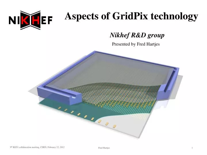
Presented by Fred Hartjes. Aspects of GridPix technology. Nikhef R&D group. Contents. Introduction into GridPix Practical directions Mechanical support Field cage HV connection DAQ Passivation Choice of the gas Peculiarities of TimePix and GridPix Time walk Cross talk.

E N D
Presented by Fred Hartjes Aspects of GridPix technology Nikhef R&D group
Contents • Introduction into GridPix • Practical directions • Mechanical support • Field cage • HV connection • DAQ • Passivation • Choice of the gas • Peculiarities of TimePix and GridPix • Time walk • Cross talk
Principle of GridPix technology • High granularity pixel chip • Cell pitch 55 – 60 μm in X and Y • Drift gap: from 1 mm (Gossip in ATLAS) on to ATLAS trigger layers (1 cm) and ILC TPC (dms) • Gas avalanche from a grid (InGrid) • Produced by wafer postprocessing • Gain 5000 - 10000 14 mm (256 columns) 14 mm (256 rows) Scaled up 4x for better visibility
GridPix functioning • Pixel chip with integrated Micromegas (InGrid) • Very small pitch • => often detecting individual electrons
100 V/mm Amplification gap 8 kV/mm Pixel chip Parallel-plate amplification field under grid • Moderate amplification field (8-10 kV/mm) • => detector might be less prone to ageing
Timepix as a pixel chip • Derived from MediPix (X-ray detection) • Matrix of 256 x 256 pixels • 55 µm pitch • => 14.08 x 14.08 mm2 sensitive area • Common clock (100 MHz) to measure drift time for each pixel • Two modes of operation • Charge arrival time to stop mode • Time-Over-Threshold (TOT) mode to measure charge signal magnitude • But both modes not simultaneously • Postprocessing to make gaseous detector • 8 µm resistive Si3N4 (SiRN) for spark protection • Amplification grid (InGrid) on TimePix InGrid
Status of GridPix production • Transferring production from MESA+ (4” wafer processing) to IZM (8” wafer processing) • TimePix chips produced on 8” wafers • December 14, 2011: successful production • Most processing done at IZM by Yevgen Bilevych • Part done at MESA+ • Deposition protective layer (SiRN) • Chemical activation of polyamide • Yield ~ 80 chips • 1st chip tried was OK • Excellent HV behaviour, good tracks seen • Possibly somewhat bigger grid distance => higher grid voltage needed • Production two additional wafers starting now • Completed end April??
Chips from 14-12-2011 run • First one tried out by Harry • Nice tracks from 90Sr • Good uniformity • No conclusive results yet • 3 other chips initially worked fine • But broken because of unsuited HV power supply (at Fermilab) 14 mm 55Fe DME/CO2 50/50
R&D on production technology • Done at MESA+ • Additional HV protection by resistive grid • Replacing SU-8 (used for pillars and dykes) • BCB • KMPR • SiO2 • GEM grid • Structures surviving cool down to 165 K of liquid Xe (XENON)
Infrastructure for TimePix • Carrier board for MUROS RO (one chip) • Relaxd RO possible • Dedicated ReLaxd boards almost finished (place for 4 chips)
In development: Octopuce • 8 TimePix chips in a structure for ILC study • Saclay (David Attié and Paul Colas) • Nikhef (Jan Timmermans) • Intermediate board up to 8 chips • Bonn (Jochen Kaminski)
Example of a field cage (100 and 20 mm) • Copper plate (guard electrode) surrounding the pixel matrix • Field shaping • By strips • By wires
HV connection needs attentionExample: TimePix with field cage Vfield Cathode plane • Filtering HV noise • Limiting discharge current from filtering capacitor • InGrid connection most precious • Use resistor 10 – 100 MΩ • Leakage current few nA • Guard potential should follow InGrid potential • Short distance => avoid sparking • HV regulation • Vgrid is the master • Vguard is the slave • Automatic remote control system is preferred Vguard Guard plane Vgrid Ingrid Voltage divider circuit
Use for Vgrid HV supply with sensitive trip • Most commercial supplies not suited • Gentle ramping not easy • No sensitive trip • May deliver output currents in mA region • => broken TimePix • Nikhef miniHV dedicated for GridPix application • Sophisticated ramping and tripping until -1000 V • Current measurement and trip setting in nA region • Versions for -2 kV and higher in development
DAQ • Systems basically developed for MediPix • MUROS (Nikhef) obsolete • ReLaxd (Nikhef) • Developed together with industry (Panalytical) • => closed FPGA code • 10 Gb system in development at Nikhef (SPIDR) • open source code • Scalable Readout System (SRS) interface for TimePix (Universities of Mainz and Bonn)
Mechanical structure of a TimePix chip equipped with InGrid • Dyke (~ 250 µm wide) surrounding the pixel matrix for mechanical termination Dyke
Passivation of edge preferred • May be OK for 400 V • He/Ar mixtures • Sparking at < 600 V • DME/CO2 etc
Passivation by Glob Top • Using Dymax type 9001-E-V-3.1 • UV curing • To be deposited in 3 – 4 layers • Slightly conductive but still low leakage current • Few nA
Choice of the gas Ar/iC4H10 80/20 • Regular drift chamber gases like Ar/He in C*H*, T2K, …… • Easy in use • Fair mobility (~ 50 µm/ns at 1 kV/cm) • Diffusion 150 – 200 µm/√cm • Best for bigger drift distance (> few cm) • Avoiding large drift voltages and long charge collection times • But paying with larger diffusion • Extreme property gas (DME/CO2) • Affects many plastics (swelling) • Very low mobility (~10 µm/ns at 2 kV/cm) • Very low Lorentz angle (~ 4°/T) • Low diffusion ~ 70 µm/√cm • Best for short drift distances (≤1 cm) • Small diffusion, beautiful tracks • Better match with small (55 µm) pixel size • Less scattering in space due to time walk DME/CO2 50/50 3 mm 3 mm
Present TimePix much hindered by time walk Measurement in DME/CO2 19.3 mm drift distance • Same event from aside and from top • Very small diffusion but big time walk From top From aside 3 mm
Indication for cross talk in the drift time spectrum Gossip (1 mm GridPix) • Time walk less dominant at high gain • But tail from small signals remains => possibly cross talk • Caused by SiRN layer (no cross talk at unprotected chip) Vg = -530 V -600 V -620 V -570 V DME/CO2 50/50
Conclusions • GridPix technology brings many benefits for accurate tracking • But one has to learn how to profit from them • Extreme gas mixtures is less easy but advantageous • Develop the photolithographic production • Newly produced InGrids are probably fine, but no conclusive results yet • Time walk will be greatly improved by dedicated front end chip (TimePix-3) • TimePix-3 has • Gossipo frontend • Very low noise level (60 – 80 e- RMS) • Peaking time 5 – 30 ns • Simultaneously measuring arrival time to stop and TOT • => time walk correction possible
Rise of pixel efficiency curve after plateau • Additional peak at charge signal spectrum • (Time Over Threshold (TOT) is indication of the magnitude of the charge signal) Vg = -480 V Vg = -440 V He/iC4H10 80/20
Hit plot (from 55Fe conversion) • Single electron hits from one 55Fe conversion • Plot focused on small signals • Larger signals all dark red • Small signal pixels(bright colour) always accompanied by a pixel having a high signal • => may be caused by cross talk
Comparing DME/CO2 to Ar/isobutane Tracks under 10° DME/CO2 50/50 Ar/iC4H10 80/20 In Y direction In Y direction
Chamber gas: DME/CO2 50/50 • DME/CO2 50/50 • Very slow and “cool” gas • High drift field required • Very low diffusion • Suited for TPC • Drift fields used in Gossips • 2 kV/cm (lowest diffusion) • 6 kV/cm (Vd = 50 µm/ns) • LHC tracking