Download
1 / 36
370 likes | 623 Views
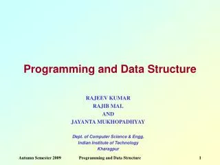
Higher Computing : COMPUTER SYSTEMS. Part 2 : Computer Structure – 6 hours. INT 2. Processor. Input. Output. Main Memory. Backing Store. Five box diagram. The five box diagram represents the basic components of a computer system.

E N D
Higher Computing: COMPUTER SYSTEMS Part 2: Computer Structure – 6 hours Higher Computing
INT 2 Processor Input Output Main Memory Backing Store Five box diagram The five box diagram represents the basic components of a computer system. It represents input devices, processor, main memory, output devices and backing storage. Computer Structure Higher Computing
INT 2 The purpose of the processor The processor – also known as the central processing unit (CPU) - is the ‘brain’ or ‘engine’ of the computer system. Its purpose is to interpret instructions and process data contained in computer programs. Computer Structure Higher Computing
INT 2 Registers Control Unit ALU RAM Parts of a processor The CPU consists of three main parts: The control unit has a timer to that sends signals to fetch, decode and execute program instructions. The arithmetic and logic unit performs arithmetic calculations e.g. / * + - and logic operations e.g. AND, OR etc. Computer Structure The registers are temporary storage areas that hold data being processed; instructions being executed; and addresses to be accessed. Higher Computing
Control Unit Operation (opcode) Input (operand) ALU Output (result) The purpose of the ALU The arithmetic and logic unit is a digital circuit that performs arithmetic and logical operations. The ALU can perform many operations including: Integer arithmetic e.g. addition and subtraction Bitwise logic operations e.g. AND, OR, NOT, XOR Computer Structure • The inputs to the ALU are the data to be operated on (called operands) • and a code from the control unit indicating which operation to perform. • Its output is the result of the computation. Marr College Higher Computing Slide 5
The purpose of the Control Unit The control unit is the circuitry that controls the flow of data through the processor, and coordinates the activities of the other units within it. It can be described as the "brain within the brain", as it controls what happens inside the processor, which in turn controls the rest of the PC. Computer Structure It performs the tasks of fetching, decoding, managing execution and then storing results and has a timer to synchronise these events. Marr College Higher Computing Slide 6
The Address Bus • Carries address information from the CPU to main memory and any other attached devices • It is uni-directional i.e. one-way only • The width (i.e. the number of wires) determines the number of memory locations the CPU can address A 32 bit address bus has 32 parallel wires each switched on (1) or off (0) that can address locations starting from: 0000 0000 0000 0000 0000 0000 0000 0000 (decimal 0) up to and including address: 1111 1111 1111 1111 1111 1111 1111 1111 (decimal 232 –1) making a total of 232 addresses Computer Structure Every time a wire is added to the width of the address bus, the address range doubles Marr College Higher Computing Slide 7
The Data Bus • Carries data to and from the CPU, main memory and any other devices attached • It is bi-directional i.e. two-way • The number of wires determines the quantity of data that the bus can carry so increasing the number of wires in the data bus increases the quantity of data it can carry • A typical 32-bit data bus can carry 32-bits of data or instructions at a time In Higher Computing we make the assumption that: The size (number of wires) on the data bus determines the size of the memory locations in RAM e.g. A 32 bit data bus means each memory location in RAM stores 32 bits (i.e. 4 bytes equivalent) Computer Structure Marr College Higher Computing Slide 8
The Control Bus - control lines Signals are sent out and received on the control bus. The control bus is not really a ‘bus’ as it does not transfer data or addresses. It is made up of discrete wires each with a specific function: • Read and Write signals are initiated to fetch – execute instructions in memory • Clock line carries a series of clock pulses at a constant rate to keep the CPU in step (clock rate measured megahertz or gigahertz) • Reset halts the execution of the stored program. Internal registers are cleared and the machine reboots. • Interrupts are signals usually from I/O devices that halt program execution temporarily. The CPU may ignore them e.g. printer out of paper • Non-maskable Interrupts cannot be ignored e.g. power failure Computer Structure Marr College Higher Computing Slide 9
Address bus Memory Address Register Other registers Data bus Memory Data Register Main Memory Control Bus (Read / Write) Arithmetic and Logic Unit (ALU) Control Unit Clock pulses Electronic clock The buses: Address, Data and Control Computer Structure Marr College Higher Computing Slide 10
The fetch-execute cycle The fetch-execute cycle of the processor refers to the sequence that is completed for each instruction in a program. • Fetch Sequence • Move the value in the program counter to the memory address register • Send the value in the memory address register to memory via the address bus • Return the value stored in memory via the data bus • Store the value in the memory data register • Copy the instruction from the memory address register to the instruction register • Increment the program counter. The instruction in the instruction register is then Decoded • Execute Sequence • Instruction is executed Computer Structure Marr College Higher Computing Slide 11
The purpose of the Registers The registers are small, fast storage areas that temporarily hold data. Instructions or addresses. The registers in the CPU have three main functions. They are to hold data being processed, instructions being executed, and addresses being accessed. • memory address register (MAR) – holds the address of a location in memory • memory data register (MDR) – holds data just read from or written to memory • program counter (PC) – holds the address of the next instruction to be fetched • Instruction register (IR) – holds the current instruction being executed • general purpose registers – can be used by programmers Computer Structure Marr College Higher Computing Slide 12
CPU Cache Main Memory (RAM) Computer Memory - Cache Cache Memory Is a small area of ‘super fast’ access memory, between the processor and main memory, which stores frequently used instructions and data. 2. CPU checks to see whether the next instruction it requires is in cache 1. Cache fetches data from next to current addresses in main memory Computer Structure 4. If not, the CPU has to fetch next instruction from main memory - a much slower process 3. If it is, then the instruction is fetched from the cache – a very fast position Marr College Higher Computing Slide 13
INT 2 RAM chip Main memory – RAM Main memory is commonly referred to as RAM (random access memory). RAM is used to hold program instructions and data before and after processing by the CPU. RAM is volatile i.e. loses it contents when switched off. Reading from RAM is slower than accessing registers or cache. Use of cache avoids slower fetches from RAM. Computer Structure Increasing memory size (capacity in Mb/Gb) improves system performance as more programs and data can be held. Higher Computing
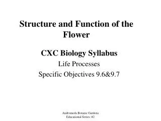
INT 2 ROM chip Main memory - ROM Another type of memory is Read Only Memory (ROM). ROM is used to store the bootstrap loader program that locates the operating system on the hard disc when the computer ‘boots up’. • Features - ROM • ROM data is permanently etched on chip • Read-only so data cannot be changed • Data not lost when computer switched off Computer Structure Higher Computing
INT 2 Backing storage Backing storage is where the computer permanently saves computer programs and data. Computer Structure This includes devices such as the hard disc and media such as DVD. Higher Computing
Distinguishing between different parts of memory Registers – fastest access time as internal to CPU Cache – slower than registers but fast as no READ needed Computer Structure RAM – slower than registers and cache Backing store – slowest speed of access Higher Computing
Task Memory • Investigate the following elements of computer memory: • Registers • cache • main memory • backing storage • Distinguish between the above elements of memory according to: • Function • speed of access • Produce a brief word processed report or powerpoint presentation. • Include an image/diagram of each component. Computer Structure Marr College Higher Computing Slide 18
Addressability Main memory consists of a number of storage locations, each of which is identified by a unique address. The ability of the CPU to identify each location is known as its addressability. Each location stores a word i.e. the number of bits that can be processed by the CPU in a single operation. Word length may be typically 16, 24, 32 or as many as 64 bits. Computer Structure A large word length improves system performance, though may be less efficient on occasions when the full word length is not used Marr College Higher Computing Slide 19
Calculating memory capacity of a computer • Memory capacity can be calculated if we know: • the number of lines on the address bus • and the number of bits stored in each memory location • Note: in Higher we assume the number of bits in a memory location to be the same as the number of bits the data bus can carry. Formula Amount of storage locations = 2 width of the address bus Memory capacity = 2 the width of the address bus * width of data bus Computer Structure Example A computer has a 24 bit address bus and a 16 bit data bus. Calculate the maximum amount of memory this computer can use. 224 * 2 bytes = 33,554,432 bytes 33,554,432 / 1024 = 32,768 kilobytes 32768 / 1024 = 32 megabytes Marr College Higher Computing Slide 20
Questions Calculating memory capacity of a computer • Calculate the total memory requirements of the following computer systems: • Processor has a 16-line address bus and each location stores 16 bits. • Processor has a 16-line address bus and each location stores 32 bits. • Processor has a 32-line address bus and a 24-line data bus. • Processor has a 36-bit address bus and a word length of 32 bits. Computer Structure Remember: Location size = data bus size = word length / size Marr College Higher Computing Slide 21
INT 2 Desktop computer Processing Power - measured by clock speed e.g. 3 Ghz. Memory size - typically 3 Gb. Backing storage – large hard disc typically 750 Gb – 1 Tb. Also, CD-RW and DVD-RW. Input devices – keyboard, microphone, mouse, webcam etc. Output devices – monitors, printers, speakers, modem etc Typical uses – applications (word, excel), email, internet, gaming Computer Structure Higher Computing
INT 2 Laptop computer Processing Power - measured by clock speed e.g. 1.75 Ghz – 2.4 GHz Memory size - typically 512 Mb – 1 Gb. Backing storage – large hard disc typically 40 - 100 Gb. Also, CD-RW and DVD-RW. Input devices – keyboard, touchpad Output devices – LCD integrated monitor, printers, speakers, modem etc Typical uses – applications (word, excel), email, internet, gaming. Portable to work on the move. Computer Structure Higher Computing
INT 2 Palmtop computer Processing Power - measured by clock speed e.g. 200 – 500 Mhz Memory size - typically 32 – 64 Mb. Can extend with memory card. Backing storage – Same as memory (battery powered) Input devices – stylus and touch screen Output devices – integrated LCD screen Typical uses – personal organiser and connectivity to PC. Computer Structure Higher Computing
INT 2 Mainframe computer A large and powerful computer that deals with very high volumes of data processing. Features Processing power: several processors RAM: 32 GB or more Backing storage: 100s of GB, tape drives I/O: keyboard, printers, monitors Computer Structure Uses Used by large organisations to provide remote access to central computer via terminals e.g. a bank’s ‘cashpoint’ machines are directly connected to a mainframe at head office. Higher Computing
INT 2 Embedded computer Embedded computers are special-purpose systems where the computer is embedded within the machine it controls e.g. a computer system in a car. They perform a specific task Considered a Computer Structure Higher Computing
INT 2 System Performance: Clock Speed Clock Speed Is the number of clock pulses a CPU generates per second. Measured in gigahertz i.e. 1GHz = 1 billion pulses per second. These pulses synchronise the steps of the fetch-execute cycle e.g. a clock pulse starts a ‘fetch’, or triggers placing data in the MDR. Computer Structure The faster the clock speed – the more operations can be executed per second. Clock speed indicates processing power but some instructions need more clock pulses on one processor than on another. Marr College Higher Computing Slide 27
System Performance: MIPS rate Millions of Instructions per Second (MIPS) MIPS roughly measures the number of machine code instructions that a CPU can execute per second. Pros Rough measure of processor performance e.g. Intel 8080: 500 kIPS at 2 MHz Intel 486 DX2: 54 MIPS at 66 MHz Intel Pentium III: 1354 MIPS at 500 MHz Intel Core 2 X6800: 27,079 MIPS at 2.93 GHz Cons No standard way of measuring MIPS as does not take into account complexity of an nstruction e.g. some instructions require more time than others. Refers only to CPU speed, not other factors such as I/O Therefore a machine with a high MIP rate may not run an application faster than a CPU with a lower rate due to other limiting factors. Computer Structure Marr College Higher Computing Slide 28
System Performance: MIPS rate How to calculate a CPU’s MIPS rating There is a simple formula to calculate MIPS. Formula MIPS = n / (t x 1,000,000) Where n is the number of instructions executed and t Example No standard way of measuring MIPS as does not take into account complexity of an nstruction e.g. some instructions require more time than others. Refers only to CPU speed, not other factors such as I/O Therefore a machine with a high MIP rate may not run an application faster than a CPU with a lower rate due to other limiting factors. Computer Structure Marr College Higher Computing Slide 29
System Performance: MIPS rate Millions of Instructions Per Second (MIP) A clock speed of 200 MHz does not mean that 200 million instructions are executed per second. Because of this, clock speed isn’t an accurate measure of performance. It may therefore be the case that two processors have the same clock speed but different MIP rates. In order to get a better picture of performance we measure the CPUs ability in how many million instructions it can process per second, also referred to as the machine cycle time. Computer Structure Marr College Higher Computing Slide 30
System Performance: MIPS rate • Working out MIPS rate • It can take at least five clock pulses to execute an instruction. • Example – a CPU with a clock speed of 200 MHz • => 200,000,000 clock pulses / 5 pulses per instruction • => 40,000,000 instructions per sec. Thus CPU = 40 MIPS Computer Structure Marr College Higher Computing Slide 31
System Performance: MIPS rate • Problems with MIPS rate • Using MIPS rate as a comparison factor also has problems. • MIPS rate depends on what sort of instructions are being carried out • There is no standard set and so some manufacturers could use instructions which require less clock pulses to complete thus giving the impression of a faster MIPS rate than it actually is. Computer Structure Marr College Higher Computing Slide 32
System Performance: FLOPS Floating Point Operations per Second (FLOPS) Measures how many floating point operations are processor can perform per second. FLOPS are more accurate than MIPS. Computer Structure They measure a number of clearly definable arithmetic tasks carried out per second. Marr College Higher Computing Slide 33
System Performance: Application-based Test (Benchmarks) Benchmarks This involves running various application programs on different computer systems and observing which system runs these programs the fastest. Most reliable measure of processor performance because it provides the user with actual evidence of how well different processors perform complex operations at high speed. Computer Structure Marr College Higher Computing Slide 34
Factors that affect system performance Data bus width – Increasing the data bus width increases processor throughput i.e. an 8-bit bus can transfer 1 byte of data; a 16-bit can transfer 2 bytes etc. Cache memory - Using / increasing cache (SRAM) means less ‘fetches’ from slower main memory (DRAM). Peripheral speed – Slow transfer rates slow the system down so better to choose peripherals with faster transfer rates. Computer Structure Marr College Higher Computing Slide 35
Current trends in computer hardware Faster clock speeds – improved CPU throughput as millions more instructions per second. More RAM – more sophisticated software can be run, and improved multitasking i.e. more programs loaded simultaneously. More backing storage capacity means more data can be stored permanently. Computer Structure Marr College Higher Computing Slide 36