Download
1 / 21
210 likes | 339 Views
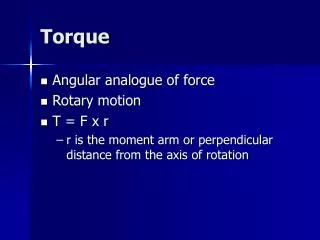
Return Torque Micro-Bearing Refit. Scott Kruse Jared Smith Jacob Reese John Anderson Cherrod Williams. Overview. Project Introduction Design Requirements Concept Generation/Selection Design Progression Material/Magnetic Selection Large-Scale Prototype Construction

E N D
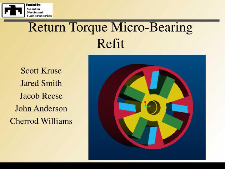
Return Torque Micro-Bearing Refit Scott Kruse Jared Smith Jacob Reese John Anderson Cherrod Williams
Overview • Project Introduction • Design Requirements • Concept Generation/Selection • Design Progression • Material/Magnetic Selection • Large-Scale Prototype Construction • FDM (Rapid Prototyping) • Magnetic Construction • Assembly • Results • Future Work
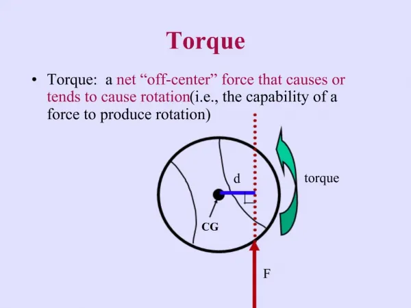
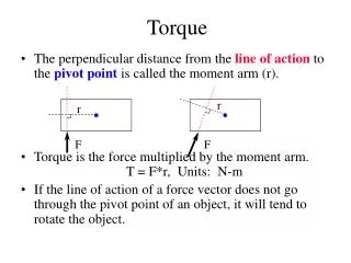
Project Introduction • Design Statement: • Design of a micro return torque bearing for actuation purposes through the use of permanent magnets • Design Specifics: • When an external torque is applied to the bearing, the bearing reacts by producing an opposing torque. • Once the external torque is removed, the bearing returns to its initial position. • Traditionally accomplished with springs.
Degrees of Travel 15 Max Torque .001 in-lb @ 15 degrees displacement Torque Requirement Monotonic (no max/min between end points) Max Diameter .1 in Max Thickness .06 in Design Requirements
Initial Chosen Concept • Variant of Concept 3 • Allows multiple moment arms • Repeatable/expandable geometry • Travel limiter inherent in design • Simple, balanced and symmetric
Design Progression • More robust design • Added magnetic material to produce necessary torque • Uses only repulsive forces to generate return torque • Better model of a spring
Chosen Material: Polysilicon • Stronger than steel • Low coefficient of friction • Extremely flexible • Directly compatible with modern IC fabrication • Used extensively in micro-machining
Magnetic Selection *Sintered NeFeB 48 was chosen for our application.
Degrees of Travel 15 Max Torque .001 in-lb @ 15 degrees displacement Monotonic Torque? Yes Diameter .08 in Thickness .06 in Results Summary
Fused Deposition Modeling (FDM) Rapid Prototyping Process • Adds layers of material instead of subtracting • Can construct complicated geometries • Fast turn around from CAD files to working prototypes • Utilizes ABS plastic
Magnet Construction • Purchased small Neodymium magnets • Set magnets in blocks of resin of the necessary geometry
Assembly • Cut Plexiglas to required diameter • Epoxied magnetic blocks in the appropriate locations • Completed the assembly by adding the parts created through FDM
Future Work • Research attachment details for the micro-scale • Run cost/benefit analysis for the replacement of springs with permanent magnets • Apply design on the micro-scale
Acknowledgements • Dr. Masson • Dr. Gielisse • Dr. Luongo • Gary the Prototype Guy • Ron Wild and Dr. Greenwood