Download
1 / 14
140 likes | 288 Views
Test of the Equivalence Principle on ISS. Ho Jung Paik, Krishna Venkateswara, M. Vol Moody Department of Physics, University of Maryland Collaborators: Inseob Hahn, Talso Chui, and Konstantin Penanen Jet Propulsion Laboratory NASA ISS Workshop on Fundamental Physics

E N D
Test of the Equivalence Principle on ISS Ho Jung Paik, Krishna Venkateswara, M. Vol Moody Department of Physics, University of Maryland Collaborators: Inseob Hahn, Talso Chui, and Konstantin Penanen Jet Propulsion Laboratory NASA ISS Workshop on Fundamental Physics October 13-15, 2010, Dana Point, CA Paik-1
Scientific Value of EP Tests In string theory, the 10-D tensor gravitational field G has two partners: scalar field (dilaton) and antisymmetric tensor field B. They are coupled to the other fields in ways generally violating the EP. Many scalar and pseudo-scalar partners of the graviton may survive as massless particles in the four-dimensional low energy world (dilatons, axions, moduli fields, etc.). The observed accelerating expansion of the universe is consistent with a cosmological constant , which is 120 orders of magnitude smaller than the quantum corrections to the vacuum-energy density. It is important to test the founding principles of GR, such as the EP, to the highest possible precision because the failure to quantize gravity and the problem may be partly due to incompleteness of GR. Paik-2
Spherical Outer Test Mass • A spherical shell approximates a point mass more closely. Smaller moments for 3 • Closure conditions satisfied: SMART test mass pairs (Example) STEP test mass pair Paik-3
Suspension and Alignment • Suspension and alignment by current along asingle tube Axis alignment 10-5 rad CMRR 108 with error compensation • Centering by currents on 4 auxiliary tubes Meander-pattern suspension coil for STEP Paik-4
Accelerometer Orientation x z y Orientations of the EP test masses with respect to the spacecraft spin axis (z) Paik-5
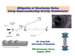
Technology Heritage • Superconducting Gravity Gradiometer (SGG) • Wire-based S/C technology • SGG for airborne gravity • Diff angular acc. • CMRR = 109 • SGG for 1-m 1/r2 law test • Diff linear accelerometer • CMRR 107 • 41013g Hz1/2 noise • Best resolution (104) of 1/r2 law at 1 m • SGG for submillimeter 1/r2 law test • Differential linear accelerometer • Search for extra dimensions to 20 m Paik-6
Levitation on a Single Tube • This critical technology has been demonstrated. Test setup • Measured frequency squared versus current squared: Sliding mode Vertical mode Screeningcurrent Wire S/C tube
P.I.: Ho Jung PaikJPL Contact: Inseob HahnJanuary 11, 2008 SMEX-ISS Concept Gate Review SMART (Standard Model And Relativity Test)
SMART: H.J. Paik, University of Maryland • Exp. module: JEM-EF, Site #9 preferred. • Goalminimum temperature: 2 K. • Science cold instrument mass: 10 kg. • Instrument power consumption:100 W. • Pointing:Rotation at 0.01 Hz about the ISS pitch (or roll) axis is required. • Science objectives: To test EP to 1017 at range 104 km. Most quantum gravity theories involve EP-violating forces. SMART tests GR and other theories beyond Einstein, and searches for new interactions and particles beyond the Standard Model. • Science team members: PI: Ho Jung Paik, U. Maryland Co-I: M.V. Moody, U. Maryland JPL Project Scientist: TB • JPL roles:Project management/ system engineering, support science instrument team, flight engineering, I&T, ATLO, CTM
Science Objectives • Science goals and objectives: To test EP and search for new interactions and particles beyond the Standard Model. • Relationship to the astronomy program objectives in NASA science plan: SMART supports NASA’s strategic goal:“Discover the origin, structure, evolution, and destiny of the universe.” • Relationship to other investigations: SMART will improve by 102 over Microscope mission, a factor of 10 short of STEP. • Justification for space: In orbit, Earth’s gravity is fully modulated,gaining 103 in signal,and accelerometers can achieve higher sensitivity (by 102-103).
Instrument • The current state of instrumentdevelopment: SMART uses superconducting differential accelerometers, which are very similar to SGG, fully developed at UM. • Diagrams of the instrument: • Mass and power:The instrument weighs 10 kg, and requires 100 W. • Limits to the sensitivity:ISS dynamic and gravity noise will be dominant. • Heritage:GP-B, which utilizes similar technologies, has flown. ISLES was supported by Microgravity Program (MP) in 2002-06. • Under NSF support, a ground ISL experiment is being performed. Detection circuit EP EP Accelerometer/ EP EP Ti-PtPt-Nb Gradiometer Nb-TiNb-Nb
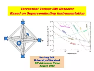
Science Traceability: Baseline Investigation Airborne SGG with CMRR = 109 ISS vibration noise spectra
Mission Design • Level of microgravity required: 10–5g. • Temperature required: 2 K with stability to better than 0.1 K. • Servicing required after installation:None. • Uplink and downlink bandwidth required:<< 0.01 Mbps, 0.2 Mbps (ref: LTMPF PIA). • ISS payload accommodation location required: The dewar needs to be rolled about the pitch or roll axis at ~10–2 Hz. Site #9 of JEM-EF is a natural site that allows this rotation. However, SMART can be accommodated at any other sites, as long as it is rotatable. • Mission time:Minimum 3-month space operation. Launch Lock & Rotation System Grapple Fixture Radiator Electronics x Payload Interface Unit (ISS/JEM-EF Interface) HTV Carrier Interface Site #9
Management: Top-Level Schedule • Science instrument • 1.5 year for Phase A/B • 0.5 year between CDR and Del to system I&T • 0.5 year system I&T at JPL • 4 month ATLO • 4 month operation in space • 6 month data analysis • JEM-EF site #9 availability is a big assumption. • But we can occupy another site with more engineering and less science. Launch EOM Start PDR SRR CDR SIR Ph F PhC PhD PhE Ph A/B Yr #4 Yr #1 Yr #2 Yr #3