Download
1 / 42
430 likes | 682 Views
RAL. ATLAS B-TRIGGER. John Baines Rutherford Appleton Laboratory, UK. On behalf of the ATLAS Collaboration. ATLAS B-TRIGGER UPDATE. Outline Introduction: LHC & ATLAS The ATLAS detector Trigger Architecture B-Physics Programme History & Recent Developments.

E N D
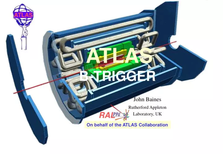
RAL ATLAS B-TRIGGER John Baines Rutherford Appleton Laboratory, UK On behalf of the ATLAS Collaboration
ATLAS B-TRIGGER UPDATE • Outline • Introduction: • LHC & ATLAS • The ATLAS detector • Trigger Architecture • B-Physics Programme • History & Recent Developments
Introduction – LHC & ATLAS 14 TeV p p • LHC: Switch on: 2007 • Peak Luminosity: 2x1033 cm-2s-1 1034cm-2s-1 • 4.623interactions per bunch crossing • Coast (fill) lasts ~10 hours • Factor ~2 drop in L during coast • ~1 per 100 interactions produce `bb • B-physics programme includes: • CP violation measurements in B-decays • Flavour Oscillations in Bs • Searches and measurements of very rare decays • Precision Measurements • Production Measurements • Requires a Highly Selective and Flexible Trigger LHC Ring
The ATLAS Detector 11m 23m
Trigger/DAQ at the LHC • High rate (40 MHz) • High granularity large event size (1-2 MBytes)
ATLAS Trigger/DAQ – Overview > Latency: 2.5ms (max) > Hardware based (FPGA, ASIC) > Calo/Muon (coarse granularity) LVL1 > Latency: ~10 ms (average) > Software (specialised algs) > Uses LVL1 Regions of Interest > All sub-dets, full granularity > Emphasis on early rejection LVL2 > Latency: few sec (average) > Offline-type algorithms > Full calibration/alignment info > Access to full event possible EF
HLT Strategy Event Selection relies on: • Processing in Steps • Alternate steps of feature extraction / hypothesis testing • Events can be rejected at any step if features do not fulfil certain criteria (signatures) • Reconstruction in Regions of Interest (RoIs) • RoI size/position derived from previous step(s) Emphasis on early event rejection Emphasis on minimising a. Processing time b. Network traffic
Region of Interest (RoI) mechanism LVL1 finds an EM cluster in the calorimeter or a muon track in the external muon spectrometer LVL2 uses LVL1 info to define a region LVL2 accesses data for that region (a few percent of the total)
HLT Strategy – Example + e30i e30i + e30 e30 e + e ecand ecand + + EM20i EM20i Signature LVL1 claims two isolated e/m clusters with pT>20GeV (possible signature: Z–>ee) Iso– lation Iso– lation STEP 4 Signature pt> 30GeV pt> 30GeV STEP 3 Strategy at HLT: > Validate step-by-step > Check intermediate signatures > Reject as early as possible Signature t i m e track finding track finding STEP 2 Signature Sequential/modular approach facilitates tuning for early rejection Cluster shape Cluster shape STEP 1 Level1 seed
HLTSSW – Design Package Interface Dependency HLT DataFlow Software Event Filter HLTSSW HLT Selection Software Processing HLT Core Software Application Level2 Steering HLT Algorithms Processing Application HLT Algorithms Data Manager ROBData Collector Event DataModel • HLTSSW runs on the L2/EF processors • Several external dependencies (Monitoring Svc, MetaData Svc, offline…)
Core Components • Steering • Controls the order in which HLT algorithms should run, given the result of the previous triggering step • All possible signatures form the Trigger Menu • All possible sequences form the SequenceTable • RegionSelector – select detectors in RoI • DataStore – stores data produced by each processing step • Convertors – convert raw data to input objects on demand – “Lazy unpacking”
HLT Select. Software: Components Package Interface Dependency HLT DataFlow Software Event Filter HLTSSW HLT Selection Software Processing HLT Core Software Application Level2 Steering HLT Algorithms Processing Application HLT Algorithms Data Manager ROBData Collector Event DataModel
Data access by an HLT algo Data Access Byte Stream Converter Data source organized by ROB Transient EventStore Region Selector Algorithm Trans. Event Store HLT Algorithm Region Selector region list DetElem IDs list DetElem IDs list DetElem IDs ROB ID raw event data Data arranged by DetElems Data arranged by DetElems DetElems: Detector Elements (e.g. Pixel wafers) IDs: Identifiers – Allow access to Geometry and mapping to ROBs For the Event Filter: data already in the TES
Event Data and Algs • Closely coupled to offline software • Common class definitions (Track, Cluster etc) • Facilitate code migration between LVL2/EF/Offline • Saves effort in development and maintenance • Makes comparisons and performance studies easier • Same arguments for data access mechanism • However, special online requirements (esp. LVL2) • Timing • Multi-threaded running
Exercising the HLTSSW • LVL1 seeding • Get list of Read-out Buffers (ROBs) for RoI, initially identified by LVL1 • Data access • Network retrieval of raw data from ROBs, on demand. • Data preparation • Unpacking of raw data into objects convenient for the reconstruction algorithms, again done on demand. • Calibration of the data objects. • Algorithm • Perform feature extraction and then hypothesis validation. For example, cluster finding and identification of the cluster. • Take Trigger Decision
ByteStream converters • Bytestream conversion process: • Raw data (as received from the detector electronics) Data objects (convenient for the HLT algorithms) • Example of data objects: Calorimeter cells with energy, position, etc… • Example of offline code used in online. • The interface to the converter is the ATLAS offline software Transient Data Store. • Creation on demand. • When the converter is called objects are only created from raw data as needed. • Caching of data. • The conversion will only happen if the data objects are not in memory already.
ATLAS Trigger Architecture Hardware (ASIC/FPGA) General Purpose Processors optimised algorithms General Purpose Processors : offline type algorithms Decision times 2 x 10⁸ 109 Hz Implementation < 2.5 s ~ 10 ms Higher Level Trigger ~ few sec FPGA = Field Programmable Gate Array ASIC = Application Specific Integrated Circuit
ATLAS B-Physics Programme The following have been evaluated for possible inclusion in the ATLAS B-physics programme: CP Violation: • Measurement of Asymmetry in: Bd J/Y (ee) K0(pp) Bd J/Y (mm) K0(pp) Control channels: B+ J/Y(mm)K+ Bd J/Y(mm)K0*(K+p-) & equiv. (ee) • Measurement of Asymmetry in: Bdp+p- + other hadron final states • Analysis ofBsJ/Y(mm)f(KK) Bs,dJ/Y(mm)h(gg) Rare decays of the type : Bd,smm(X) • Branching fraction for Bd,sm+ m- • Branching fractions for: Bdr0mm and Bd K*0mm • F-B Asymmetry in Bd K0*mm sin2b |Vtd| / |Vts| Searches for: B K+K-p- Precision measurements, eg. • Bc measurements : Bc J/Y(mm) p, Bc J/Y(mm) mn • Lb polarisation Lb J/Y(mm)Lo(pp) CP-viol. ampl. a,b (sin2a) DGsGs A// A d2-d1z Measurement of Bs oscillations: • Bs Dsp and Bs Ds a1 with Dsfo(K+K-)p Note: The B-physics programme will be discussed in detail in the ATLAS Physics Overview talk. Dms
History & Recent Developments • ATLAS B-trigger strategy outlined in the DAQ and High Level Trigger Technical proposal in 2000 • Since then, • Possibility of reduced detector at start-up: • TRT only at |h| < 2 (c.f. full TRT |h| < 2.5) • Only 2 of the 3 Pixel layers (inner “B-layer” maintained) • Need flexibility to cope with evolution of detector ~ • Target for LHC startup luminosity is now 2 x 1033 cm-2 s-1, although: • Actual start-up luminosity uncertain • Luminosity may vary fill to fill • During a coast luminosity is expected to fall by a factor ~2 • Re-evaluate trigger thresholds (single muon pT threshold and ID reconstruction thresholds) • Assess impact of removing triggers requiring the most resources (e.g. J/y(ee)) • Develop flexible trigger strategies - possibility to include more B-triggers as luminosity falls, e.g. • di-muon trigger only at L = 2x1033 cm-2s-1 • add other triggers as L decreases (e.g. B(pp), Ds(fp) based on ID full-scan or low ET RoI) • Financial constraints • Investigate new possibilities for reducing resource requirements e.g. • Low ET Level-1 calorimeter RoI used to guide reconstruction at Level-2 • Level-2 RoI used to limit region for reconstruction at the Event Filter • LHC delayed, start-up now expected in 2007 • Main c.p.u purchase delayed to 2006 (cheaper/faster c.p.u – expect 180 SpecInt95 = 4.5 GHz PC) l RoI = Region of Interest ~
ATLAS B-TRIGGER UPDATE • Outline • Trigger Strategy : • Final states including two muons • Hadron Final States • Muon Trigger • Rejection of m from p/K decays • Based on ID full-scan: • Inner Detector (ID) • ID Full-Scan • Bd(pp) trigger • Ds(f(KK),p) trigger • Alternative based on Calorimeter RoI • Final states with electrons and muons • TRT Full-scan • J/y(ee) trigger • Alternative using calorimeter EM RoI RoI = Region of Interest
Trigger for Di-Muon Final States e.g. Bd J/Y(mm)(K/K*) Bs J/Y(mm)f,h B mm B K0*mm, etc. LbL0 J/Y(mm) Bc J/Y(mm)p Level-1 Level-2 & EF • At Least 2 Muons: • Minimum thresholds: • Muon Barrel: pT > 5 GeV • Muon End-Cap: pT > 3 GeV • Actual thresholds used will be • determined by rate limitations • Confirmation of Muons in: • Precision Muon Chambers • Inner Detector • EF Selections: • Refit ID tracks in Level-2 RoI • Decay vertex reconstruction • Select J/y(mm) B(mm) etc. using mass & decay length cuts • Search for hadrons from • B K0*(h,h)mm, etc. • Select using mass cuts ~ ~ • TotalRate ~ 20 Hz • (L= 2 x 1033cm-2s-1) • Level-1 Di-Muon triggers mainly due to: • muons from heavy flavour decays • single muons giving double trigger in • end-cap trigger chambers • Rate ~600 Hz(pT > 6 GeV threshold, • L= 2 x 1033cm-2s-1)
Hadron Final States Bs Dsp, Bs Ds a1 Dsfop, fo K+K- Bdp+p- >1 Muon: pT > 6 - 8 GeV Plus: >1 Jet cluster ET > 5 GeV ~ e.g. Level-2 & EF Level-1 At Least 1 Muon: pT > 6 - 8 GeV • Refit ID tracks in Level-2 RoI • Decay vertex reconstruction • Mass & Decay length cuts. • Confirmation of Muon in: • Precision Muon Chambers • Inner Detector • Full-Scan of Inner Detector • Mass cuts Full-Scan • Confirmation of Muon in: • Precision Muon Chambers • Inner Detector • Confirmation of Jet in • calorimeter • Scan of ID in Jet RoI • Mass Cuts • Refit ID tracks in Level-2 RoI • Decay vertex reconstruction • Mass & Decay length cuts Options RoI-Guided
The Muon Trigger Muon Trigger Chambers (TGC) • Level-1 trigger from Muon Trigger Chambers • Muon confirmed at Level-2 using Precision Muon Chamber Data • 20 points per m, resolution ~ 80mm Better track measurement allows tighter threshold. • Muon confirmed in Inner Detector: • Extrapolate Muon track to ID, • Search for ID track. • Combine parameters & apply matching cuts. Muon Trigger Chambers (RPC) Muon Precision Chambers (MDT) Inner Detector RPC: Restive Plate Chambers TGC: Thin Gap Chambers MDT: Monitored Drift Tubes
Rejection of p/K m decays • Level-1 Single Muon Trigger: • Rate: ~20kHz • pT > ~6 GeV @ L=1033 cm-2 s-1 • Most arem from p/K decay • with true pT < 6 GeV • Level-2 Muon Confirmation: • Using Precision Muon Detector info.: • Better track measurement • allows tighter threshold. • Rate: ~9 kHz • 35% b m and c m, • 65% p/K m • Using Combined Muon & ID info: • Single Muon Trigger • Rate:~5 kHz@L=1033 cm-2 s-1 • ~50% p/K m 100 80 60 40 20 0 Efficiency (%) LVL2 muon standalone 0 2 4 6 8 10 12 14 muon pT (GeV) 100 80 60 40 20 0 Efficiency (%) • Raising threshold by 2 GeV • ~ factor 2.5 rate reduction e.g. pT > ~8 GeV (m8) • Rate ~ 2 kHz@L=1033 cm-2 s-1 LVL2 muon + ID 0 2 4 6 8 10 12 14 muon pT (GeV)
An HLT Algorithm: T2Calo • LVL2 clustering algorithm for electromagnetic (EM) showers, seeded by LVL1 EM RoI positions. • Main variables built: (1) Energy of EM clusters (2) Associated Hadronic Energy
An HLT Algorithm: T2Calo (cont) (3) E3x7/E7X7 in Layer 2 (4) (E1-E2)/(E1+E2) in Layer 1 background signal
System performance • Conditions of the measurements: • RoI of (Dh x Df) = (0.3 x 0.3). • Dijet events at low luminosity with pileup. • Machine: CPU 2.4 GHz Xeon with 1 GByte of memory. • Measure minimum time that the data converter function would take using no offline-inherited code. • Remember: Average LVL2 processing budget is ~10 ms. Largest contribution is from Data Preparation Algorithm is the smallest contribution New offline-compatible version incorporating these and other improvements approaches performance requirements (now 3-4 ms for data preparation)
ATLASInner Detector Transition Radiation Tracker (TRT) : Straws 40 cm - 70 cm long filled with Xe/CO2/CH4. Single sense wire per straw. ~36 measurements along track. Two readout thresholds - Electron ID via higher threshold Transition Radiation hits See Inner Detector Talk for more details h=2.5 1.2m 3.5m Pixel Detector : Si wafer: 2.1 cm x 6.5 cm with 50 mm x 300/400 mm pixel r/o. 2(3) measurements along track. Inner layer at R = 5.05 cm • SemiConductor Tracker • (SCT) • Si micro-strip detector: • 6.4 cm x 12.8 cm. • 80 mm r/o pitch. • Barrel: 4 cylinders; • End-cap: 9 Wheels each with • 2 stereo layers: f + u or v (40 mRad) • 8 hits along track i.e. 4 space-points.
IDscan - Inner Detector full-scan Pixels • Hit Filter: • Forms groups of hits- group contains the hits from a track; may also contain some extra nearby hits • Use muon track to define Z of vertex of primary i.p. • Form 2D (h,f) histogram of SCT & Pixel hits • Select hits in bins with >3 layers hit • Group hits from neighbouring bins • Group Cleaner: • Select the hits from a group forming a track candidate • Determine f0 and r for hit triplets • Fill 2D histogram in f0,1/pT • Bin with hits from >4 layers => track candidate • Track Fit: • Determine track parameters IDscan Algorithm SCT • Start with the Pixels and SCT: • Less affected by material interactions • 3-D measurements • Full |h| coverage from start-up
B h+h- Trigger Bdpp Events + min. bias • Two opposite sign tracks with: • pT + pT > 10 GeV • Dz0 < 2 cm • 4.3 < M(pp) < 6.3 GeV + - 0 2 4 6 8 M(p+p-) (GeV) No. Events axy Decay Vertex No. Pixel Layers Efficiency for B pp events with pile-up (L = 1033 cm-2s-1): B pp events, pT (p,p)> 4 GeV B pp events selected offline Background B mX events Level-2 rate ~20 Hz for 2 kHz m8 EF selection reduces rate to ~3 Hz 2 3 78% 80% 89% 93% 1.1% 1.1% • Level-2 selection: • Tracks separated from trigger m • by DRfh> 0.2 • pT > 3.9 GeV 100 80 60 40 20 0 • Event Filter Selection: • Tighter mass cut • Vertex fit cuts : • c2 / Nd.o.f. < 8, • Lxy > 100 mm, • axy< 5 Level-2 Efficiency (%) Bd pT spectrum both p pT>4 GeV y o Lxy 10 15 20 25 30 35 40 45 50 pT of Bd (GeV) x
Dsf(KK)p Trigger Signal Events + min. bias 1.25 1.5 1.75 2 2.25 0.95 1 1.1 1.2 M(KKp) (GeV) M(KK) (GeV) • Level-2 Efficiencies for Bs Ds(f(KK))p • events with pile-up (L = 1033 cm-2s-1): • Signal events with • pT (p,p and K) > 1.5 GeV • Signal events selected offline • Background B mX events • Level-2 Trigger rate ~60 Hz for 2 kHz m8 • EF selection reduces rate to ~9 Hz • Level-2 Selection: • Tracks: pT > 1.4 GeV • DRfh> 0.2 w.r.t. trigger m No. Pixel Layers 2 3 69% 68% 78% 79% 3.5% 3.8% • Two opp. sign tracks satisfying: • M(KK) - M(f) < 17 MeV • Third track with: • M(KKp) - M(Ds) < 74 MeV • EF Event Selection: • Tracks: pT > 1.5 GeV • Mass cuts : • M(KK) - M(f) < 14 MeV • M(KKp) - M(Ds) < 56 MeV • f vertex fit cuts: • c2 prob. >0.5%, Lxy >200mm • Ds vertex fit : • c2 prob>0.5%, Lxy > 200 mm Signal Events + min. bias Events / 20 MeV Events / 2.5 MeV K+p o
Alternative Using Level-1 Jet RoI to guide B-physics Triggers Jet RoI Multiplicity (ET > 5 GeV) 0 1 2 3 4 5 6 7 8 9 Jet RoI Multiplicity • Preliminary studies of an alternative to the full-scan using, instead, low ET Level-1 RoI to define regions to search ID at LVL2 • Studied using fast simulation + parameterisation of calorimeter • Jet RoI (0.8 x 0.8 cluster) ET > 5 : • Mean Multiplicity = 1.7 • (BmX events, m pT > 6 GeV) • Reconstruct tracks at Level2 inside regions • e.g. for B(pp) and Ds(fp) ~ No. Events • LVL2 reconstruction inside RoI corresponding to ~10% of ID acceptance • potential to save ~factor 10 execution time c.f. full-scan • but with lower efficiency
Using Level-1 Jet RoI to guide B-physics Triggers 1 0.8 0.6 0.4 0.2 0 Efficiency • B p p • pTp> 4 GeV • RoI ET> 5 GeV 0 5 10 15 20 25 30 B hadron pT (GeV) 1 0.8 0.6 0.4 0.2 0 Efficiency • B Dsf • pT Ds, f> 1 GeV • RoI ET> 5 GeV 0 5 10 15 20 25 30 B hadron pT (GeV) Efficiency for Jet RoI within |Dh| < 0.4, |Df| < 0.4 of B hadron Based on fast simulation + calorimeter parameterisation Actual efficiencies and c.p.u. savings depend on thresholds & multiplicities => to be studied using full simulation
RoI Guided Reconstruction at the Event Filter 0 0.5 1 1.5 2 2.5 3 2 1.5 1 0.5 0 Bdp+p- Dh Dh 0 0.5 1 1.5 2 2.5 3 Df 2 1.5 1 0.5 0 Dh Dsf(K+K-)p • Following Level-2 B-trigger selection: • Use Level-2 to guide reconstruction at the Event Filter • Level-2 defines a region which contains all tracks forming Ds(fp), B(pp) candidates • Region corresponds to ~10% of the Inner Detector acceptance • Factor ~10 saving in resources compared to full reconstruction Df
e.g. `bb eX Bd(J/Y(mm)K0) Electron & Muon-Electron Final States `bb mX Bd(J/Y(ee)Ko) Level-2 & EF Level-1 • Refit ID tracks in Level-2 RoI • Decay vertex reconstruction • Mass & Decay length cuts At Least 1 Muon: pT > 6 - 8 GeV • Confirmation of Muon in: • Precision Muon Chambers • Inner Detector • Full-Scan of Inner Detector (SCT, Pixels & TRT) • Mass cuts Full-Scan >1 Muon: pT > 6 - 8 GeV Plus: >1 EM cluster ET > 2 GeV • Confirmation of Muon in: • Precision Muon Chambers • Inner Detector • Confirmation of electron in EM RoI using: • Calorimeter • Inner Detector • Possible search for second electron • Refit ID tracks in Level-2 RoI • Decay vertex reconstruction • Mass & Decay length cuts Options RoI-Guided
TRT-SCAN 1/pT f0 • Each hit straw populates a set of bins forming a line in the histogram in transform space (f0,1/pT) or (f0,1/pL). • Maxima in the histogram correspond to track candidates. • Track search using a Histogramming method based on a Hough Transform. • Track trajectories are described by: (f0,pT) - barrel and (f0,pL) - endcap. • Sets of trajectories are defined with discrete steps in f0 and 1/pT or 1/pL. • Each trajectory corresponds to a histogram bin. Histogram for a single muon 30 20 10 0 No. of hits along trajectory (f0, 1/pT) • Track candidates are examined and can be split or merged if required. • A track fit is performed to improve the track parameter resolution. Drift time information can be included at this stage. Set of trajectories through a straw • Execution time scales linearly with: • inverse pT(pL) threshold • no. hits in event
J/y e+e- Trigger Level-2 Efficiencies for Bd J/y(ee)Ks events with pile-up (L = 1033 cm-2s-1) Recon. tracks pT > 0.8 GeV: 40% : Signal events with pT (e,e) > 1 GeV 53% : Events selected offline 2% : Background B mX events Level-2 Trigger rate ~40 Hz for 2 kHz m8 EF selection reduces rate to ~4 Hz • Level-2 Selection: • Tracks: pT > 0.5 - 1.5 GeV • Identified as electrons by TRT • Two opposite-sign e tracks with: • pT + pT > 4 GeV • | Dh | < 1.4, | Dz0 |< 2 cm • cos(qee) > 0.2 • 2 < M(ee) < 3.5 GeV + - Signal Events + Min. Bias • Event Filter Selection: • Tighter mass cuts • Vertex fit cuts : • c2 / Nd.o.f. < 8, • Lxy > 220 mm, • axy< 40 0 1 2 3 4 5 M(ee) (GeV) o
Alternative Using Level-1 EM RoI h separation J/y e+e- • Preliminary study of the possibility of using calorimeter to provide RoI to search for low pT electrons at level-2 for J/y(ee) and m-e • EM RoI ET>2 : • Mean Multiplicity = 1.1 (B->mX , m pT > 6 GeV) • Effic. to tag both e in J/y(e,e) : 80% (e pT >3 GeV) e pT > 0.5 GeV Fast Simulation + Calorimeter Parameterisation No. Events • If both electrons found at Level-1: • confirmation at Level-2 inside small region about each electron • If only one e found at Level-1, could search larger region for 2nde • Level-2 Reconstruction in ~10% of ID acceptance 0 0.5 1 1.5 2 e+e- separation Dh f separation J/y e+e- Efficiency 1 0.8 0.6 0.4 0.2 0 RoI Multiplicity EM RoI ET > 2 GeV 90% e pT > 0.5 GeV Efficiency for e from B e No. Events No. Events RoI ET > 2 GeV 0 1 2 3 4 5 6 7 8 9 0 2 4 6 8 10 12 14 0 1 2 3 electron pT (GeV) RoI Multiplicity e+e- separation Df
Execution Times • Execution times measured on a different platforms • Determine scaling with occupancy • Times scaled to a 4 GHz PC (assumed 160 SpecInt 95) • Used to estimate resources needed for B-trigger Execution Times Scaled to 4GHz PC 30 20 10 0 IDscan IDscan Execution Time (ms) No. Events Linear scaling with occupancy 0 2000 4000 6000 8000 10000 0 20 40 No. space-points in Event Execution Time (ms)
Resource Estimates • Study several options for B-physics triggers: • Chosen to represent a broad range of possibilities • Do not necessarily reflect final choices Resources additional to those needed for full menu of high pT triggers • di-muon triggers only (1) Minimal additional resources • di-muon trigger when L > 2x1033 cm-2s-1 • Add B(hh) and Ds(fp) triggers for L < 2x1033 cm-2s-1 • based on ID full-scan for events with muon pT > 8 GeV ~ (2) Requires some additional resources ~ • B-trigger based on level-1 RoI : • di-muon trigger • B(pp), Ds(fp), J/y(ee) etc. based on Level-1 EM Jet & • EM RoI (3a) Requires additional resources, but less than (2) • B-trigger based on level-1 RoI: • di-muon trigger when L > 2x1033 cm-2s-1 • Add B(hh), Ds(fp), J/y(ee) etc. triggers for L < 2x1033 • based on Level-1 EM Jet and EM RoI (3b) ~ Modest additional resources ~
Summary • The ATLAS B-trigger strategy was outlined in the DAQ and High Level Trigger Technical proposal in 2000 • Since then, B-trigger strategy has been re-assessed in the light of: • LHC luminosity target for start-up doubled to 2 x 1033 cm-2s-1 • Detector changes, including possibility of reduced detector at start-up • Need to minimise trigger resources in the light of financial constraints • Develop flexible B-trigger strategies to: • Cope with evolution of detector • Provide possibility of adding more B-triggers as luminosity falls • Investigate new possibilities for reducing resource requirements e.g. • Low ET Level-1 calorimeter RoI used to guide reconstruction at Level-2 • Level-2 RoI used to limit region for reconstruction at the Event Filter • As a result ATLAS hopes to pursue a full programme of B-physics from LHC start-up • Next review stage is the Technical Design Report (2003) – some architectural choices must be made based on physics simulation studies, prototyping and full system modelling. Ready for first Physics in 2007