Download
1 / 35
350 likes | 550 Views
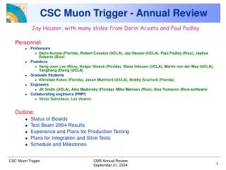
CSC Muon Trigger. Jay Hauser Director’s Review Fermilab, Apr 30, 2002. Outline The CSC muon trigger design Project scope Fall 2000 prototype test Pre-production prototype to be tested Summer 03 Conclusions. CMS Endcap Muon System. 3 or 4 stations Each CSC chamber has six planes:

E N D
CSC Muon Trigger • Jay Hauser • Director’s Review • Fermilab, Apr 30, 2002 • Outline • The CSC muon trigger design • Project scope • Fall 2000 prototype test • Pre-production prototype to be tested Summer 03 • Conclusions
CMS Endcap Muon System • 3 or 4 stations • Each CSC chamber has six planes: • Radial cathode strips for precision muon position and bend direction measurement • Anode wires for timing (bunch ID) and non-bend position measurement
Geometric Coverage ME4 descoped
Trigger requirements • Cathode LCT • Identify cathode track segment. Pt trigger based on angle of LCT • For Pt threshold of 20-40 GeV requires Dp/p < 30% (in order to limit single muon trigger rate in Level-1 to a few KHz) • Track hits must be located to within ½ strip width in each chamber layer • Anode LCT • Form anode track segment. • Tag bunch crossing of track segment with > 92 % efficiency per chamber
CSC Trigger Efficiency vs. PT 10 20 Trigger threshold defined at 90% efficiency 40 60 Sharper turn-on for better PT resolution Require ME1 for good PT resolution 1.2 < || < 2.4
CSC Trigger Efficiency vs. Loose: 2 or more stations including ME1 in endcap, but any two in DT/CSC overlap region~97% efficiency Tight: 3 or more stations including ME1 in endcap and MB1 in DT/CSC overlap ~70% efficiency but better PT resolution
CSC Single Muon Rate || < 2.1 Require “tight” track conditions ( 70%)to get acceptable rate from standalone CSC trigger Rate must be less than few kHz Multiply by 5 for L = 1034
Trig Motherboard Clock Control Board DDU Board DAQ Motherboard C C B D M B T M B D M B T M B D M B T M B D M B T M B D M B T M B M P C T M B D M B T M B D M B T M B D M B T M B D M B Slow Control C O N T R O L L E R Muon Sector Receiver Lev-1 Trigger Readout Data Trigger-Timing-Control Peripheral Crate on iron disk FED Crate in XSC55 1 of 5 1 of 5 Cathode Front-end Board CFEB CFEB CFEB CFEB CFEB 1 of 2 LV Distribution Board 1 of 24 ALCT LVDB Anode LCT Board Anode Front-end Board CSC Endcap Muon Trigger Primitive Generation
Main FPGA (on back) XILINX XCV1000E Input connectors From 5 CFEB’s Mezzanine board Input connectors From ALCT Trigger Motherboard (TMB) • Source of CSC trigger primitives for 1 chamber: sent on backplane to Muon Port Card (MPC) • Other functions: • Generates Cathode LCT trigger with input from CFEB (comparator) • Matches ALCT and CLCT; sends anode hits to DMB.
CSC Muon Trigger Scheme On-Chamber Trigger Primitives 3-D Track-Finding and Measurement Muon Port Card Trigger Motherboard Strip FE cards Sector Receiver Sector Processor LCT OPTICAL FE SR SP PC LCT TMB 3 / port card FE 2 / chamber 3 / sector Wire LCT card Wire FE cards In counting house RIM CSC Muon Sorter RPC Interface Module RPC DT 4 4 4 Combination of all 3 Muon Systems Global L1 Global Trigger 4
Prototype version tested Fall 2000: New version (SR/SP combined) Scope of CSC Trigger Project Baselined with 24 crates, reduced to 6 in 1998, now 1:
Prototype Test in Fall 2000 • Muon Port Card produces CSC muon segment data • Data sent over Giga-bit optical link • Sector Receiver receives and formats data • Formatted data sent over backplane • Sector Processor links CSC muon segments into track, assigns PT, f, h • Hardware operated at full 40 MHz speed • Results compared bit-for-bit with simulation • Perfect agreement attained
DAQ System (VME, Bit3 Controller, PC running Windows NT) Port Card Sector Receiver Sector Processor FIFO FIFO FIFO FIFO FIFO FIFO 100m Optical Links Custom Back plane Track Finder Prototype • FY 2000 focus was on producing and testing a Track Finder prototype: • Items produced: • Backplane (Florida) • Sector Processor (Florida) • Muon Port Card (Rice) • Clock and Control Board (Rice) • Sector Receiver (UCLA) • Test software support (all) • Results included in Trigger TDR (Oct. 2000): • Input data bits loaded into Port Card or SR • Data clocked through MPC SR SP at full speed • Results examined for validity
Muon Port Card Prototype VME Interface Optical links Main FPGA on Daughter Card
Sector Receiver Prototype Optical Receivers and HP Glinks UCLA SRAM LUTs Front FPGAs Back FPGAs
Sector Processor Prototype Final Selection UnitXCV150BG352 Extrapolation UnitsXCV400BG560 Florida 12 layers 10K vias 17 FPGAs 12 SRAMs 25 buffers Assignment UnitsXCV50BG256 &2M x 8 SRAM Track Assemblers256k x 16 SRAM Bunch Crossing AnalyzerXCV50BG256
1st Track-Finder Crate Tests Clock Control Board (Rice) Bit3 VME Interface Custom Backplane (Florida) Muon Port Card (Rice): Sector Processor (Florida): Prototype crate for original six crate design tests very successful but latency too high -- New design in 2001 Sector Receiver (UCLA): 100m optical fibers
New EMU Trigger Design:U. Florida Track-Finder Track - Finder crate (1.6 Gbits/s optical links) SP 2002 Card (3 Sector Receivers + Clock and Control Board Sector Processor) SR SR SR SR SR SR SR SR SR SR SR SR CCB ° / (60 sector) / / / / / / / / / / / MS SP SP SP SP SP SP SP SP SP SP SP SP BIT3 Controller From MPC (chamber 4) Muon Sorter From MPC (chamber 3) From MPC (chamber 2) From Trigger Timing Control From MPC (chamber 1B) From MPC (chamber 1A) To To DAQ Global Trigger · Power consumption : ~ 1000W per crate · 16 optical connections per SP · Custom backplane for SP CCB and MS connections
New 1-Crate Design Meets Latency Requirement First prototype dataflow Pre-production prototype data flow From Muon Port Cards From Muon Port Cards Optical receivers Optical receivers Front FPGAs 1 Front FPGAs 1 Sector Receiver st.4 Sector Receiver st.1 Sector Receiver st.2,3 To DT Lookup tables 1 Lookup tables 1 SR/SP board Channel link transmitters 0 Bunch crossing analyzer (not implemented) 4 Channel link receivers 1 Extrapolation units Latency Latency Bunch crossing analyzer (not implemented) 1 2 9 Track Assembler units Sector Processor FPGA Extrapolation units 3 1 Final selection unit 3 best out of 9 Pt precalculation for 9 muons 9 Track Assembler units (memory) 2 Final selection unit 3 best out of 9 3 1 Output multiplexor Sector Processor Pt precalculation for best 3 muons 3 1 Pt assignment (memory) Pt assignment (memory) 2 Total: 7 BX Total: 21 BX To Muon Sorter To Muon Sorter
Description of CSC Trigger System Elements • MPC (Muon Port Card) • Source of muon segment data from chambers • SR/SP (Sector Receiver/Sector Processor) • Links segments into tracks with known momentum • CCB (Clock & Control Board) • Clocking and interface to global control system • CSC Muon Sorter • Collects tracks for transmission to Global Muon Trigger • Track Finder crate backplane • DDU (Detector-Dependant Unit) • For readout, used for diagnostics for the trigger
New MPC Design (Rice) 9U x 400 MM BOARD VME J1 CONNECTOR VME INTERFACE UCLA MEZZANINE CARD (XCV600E) CCB CCB INTERFACE SORTING LOGIC INPUT ANDOUTPUT FIFO CCB TMB_1 OPTO SER TMB_2 CUSTOM PERIPHERAL BACKPLANE 3 OPTICAL CABLES TO SECTOR PROCESSOR TMB_3 OPTO SER TMB_4 TMB_5 TMB_6 OPTO SER TMB_7 FINISAR FTRJ-8519-1-2.5 OPTICAL TRANSCEIVERS TMB_8 TLK2501 SERIALIZERS FPGA TMB_9 SN74GTLP18612 GTLP TRANSCEIVERS
Optical Link Radiation Tests • Three serializers: up to 270 kRad TID.No permanent damage or SEU • Two Finisar optical modules: No errors up to 70 kRad. • Failed at ~70kRad(well above~10 kRad TIDinner CSCdose for10 years) • -- Rice
Sector Processor 2002 Board Layout DC-DC Converter Phi Global LUT EEPROM Eta Global LUT Phi Local LUT EEPROM EEPROM Indicators VME/CCB FPGA TLK2501 Transceiver From CCB Front FPGA PT LUT TRANSITION BOARD WITH LVDS TRANSCEIVERS TO/ FROM BARREL DDU FPGA To MS Main FPGA Optical Transceiver Mezzanine Card
MAIN FPGA FRONT FPGA ETAG LUT 512K x 18 Flow Through SRAM PhiB_G - 5 PHIL LUT 256K x 18 Flow Through SRAM PhiB_L - 6 CLCT PAT# - 4 A18 Phi_L - 2 Q - 4 Phi_L -10 Eta_G- 7 CLCT_ID - 8 CSC_ID - 4 PhiB_L - 6 L/R -1 WG_ID - 7 C3 CSC_ID – 4 WG_ID – 7 A11 CSC ID - 4 CLK40P1 C3 PHIG LUT 512K x 36 Flow Through SRAM Phi_G-12 16 Bit Transceiver Phi_L - 10 D16 WG_ID - 5 CSC_ID - 4 Phi_DT - 12 C2 To DT C4 CLK40P2 D12 16 Bit Transceiver C2 Legend: A – Address Lines D - Data Lines C – Control Lines CLK – Clock CLK40 CLK40 ME1 SR LUT Triad • 45 synchronous memories for conversion of 15 track segments • >64 MB per board Need high VME bandwidth, broadcast capability to identical chips, and crate broadcast capability to SPs
9xD24 ME2/ ME4 STUBS MAINFPGA 9xD5 C3 MUX 3xD1 3xD12 + 4xD1 6xD24 ME1 STUBS PT LUT 3xA22 6xD9 3xD8 3xC4 2xD1 3xD8 DT STUBS 2xD25 TRAN D8 3xD8 3xC1 DDUINT C2 C1 C4 Legend: G – Number of Signal Groups GxAn – G Groups of n Address Lines GxCn – G Groups of n Control Lines GxDn - G Groups of n Data Lines TRAN - Transceiver CCB&VME Int – Combined CCB and VME Interface CFG ROM – Configuration ROM CLK40 – Clock 40 MHz DDU- INT – Readout Interface D32 C2 CCB& VME INT CFG ROM C9 CLK40 C3 A8 D16 Main Sector Processor FPGA • Placed on mezzanine card • Firmware written in “Verilog++” and implemented in ORCA as well • Latency only 4 BX
TTCrx mezzanine board CCB for Track Finder Crate • Same CCB for peripheral and Track Finder crates • 20 sets (main 9U board + Altera-based mezzanine card) have been fabricated so far • 15 boards are assembled and tested • 2 boards will be used for Track Finder tests (UF & Rice)
Sorter FPGA MUON 1 DFF TMB 1 MUX PIPELINE MUON 1 DFF MUX 4 FIFO_B MUON 1 VME FIFO A VME MUX PIPELINE MUON 2 DFF MUON 2 DFF 4 VME FIFO A FIFO_B MUON 2 TMB 2 VME • • MUON 3 DFF • TMB 9 VME FIFO_B MUON 3 54 SORTER “3 OUT OF 18” CCB 9 VME CCB INTERFACE WINNER
CSC Track Finder Backplane Standard VME 64x J1/P1 backplaneA24/D16 (but D32 possible using address lines) SRSP 1 SRSP 2 SRSP 3 SRSP 4 SRSP 5 SRSP 6 Clock and control Muon sorter SRSP 7 SRSP 8 SRSP 9 SRSP 10 SRSP 11 SRSP 12 Standard VME J2/P2 backplane Custom GTLP 6U backplane Signals specified, routing to commence
Mirror CSC DAQ Path OSU now plans 20° slices to equalize bandwidth CSC DDU designed by Ohio State Univ. 15 optical fibers 36 Sector Processors send L1 data 12 optical fibers + 1 DDU SLINK
CSC Trigger Status/Plans • Prototype 1 tests now complete • Prototype 2 and production follow EMU components to optimize technology • MPC, SP, CCC modules, backplane* milestones: • Apr-02 Prototype 2 designs done • Freeze CSC-DT interface • Determine DDU compatibility with OSU module for EMU • Nov-02 Prototype 2 construction done • Apr-03 Prototype 2 testing done • Sep-03 Final designs done • Oct-04 Production done • Apr-05 Installation done (*backplane schedule ~3 months ahead of above dates to provide platform for testing and integration) • Muon Sorter module: only 1, design by Jan-04
CSC ‘02 Milestones • Syst. Item Action Date Status Comment • CSC Bckpl Specified Dec-01 Done OK • CSC Bckpl Proto done Jun-02 Delay: Aug-02 OK • CSC CCB Proto done Jun-02 Delay: Aug-02 OK • CSC SR/SP Proto done Sep-02 Delay: Nov-02 OK • CSC Bckpl Proto tested Sep-02 Delay: Apr-03 OK • CSC MPC Proto done Sep-02 OK • CSC CCB Proto tested Sep-02 Delay: Apr-03 OK
Personnel • Professors • Darin Acosta (Florida), Robert Cousins (UCLA), Jay Hauser (UCLA), Paul Padley (Rice) • Postdocs • Song Ming Wang (Florida), Benn Tannenbaum (UCLA), Slava Valouev (UCLA) • Students • Bobby Scurlock (Florida),Jason Mumford (UCLA) • Engineers • JK (UCLA), Alex Madorsky (Florida), Mike Matveev (Rice), Ted Nussbaum (Rice) • Collaborating engineers (all PNPI) • Victor Golovtsov, Lev Uvarov
Coordination and Oversight • Four institutions: Rice, UCLA, UF, UW • Central link to all documentation: • http://afs-web.hep.wisc.edu/~wsmith/cms/trig_pm.html • Monthly progress reports • Videoconferences ~6 weeks • 2-day meetings 3x or 4x per year, rotate between Rice, UCLA, and UF, minutes posted • UF, March 22-23, 2002 • UCLA, Dec. 14-15, 2001 • Rice, Aug 14-15, 2001 • etc
Conclusions • First Track Finder system prototyped successfully in Fall 2000 • Exact match to CMS OO simulation package • Second generation pre-production prototype is well underway with significant improvements • Present and future activities • 2001: R&D on optical links, FPGA logic, memory look-ups, backplane technology, and DAQ readout • 2002: build the 2nd generation prototype • 2003: test with multiple CSC chambers, cosmic rays and/or structured beam, tweaks for final design (if necessary) • 2004: full production • 2005: installation • No trouble expected: all-digital system with off-the-shelf components, well-defined internal and external interfaces, and a stable and capable engineering team