Download
1 / 22
220 likes | 361 Views
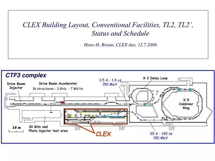
CLEX Building Layout, Conventional Facilities, TL2, TL2’, Status and Schedule Hans-H. Braun, CLEX day, 12.7.2006. CTF3 complex. X 2 Delay Loop. 3.5 A - 1.4 m s 150 MeV. Drive Beam Accelerator. Drive Beam Injector. 16 structures - 3 GHz - 7 MV/m. TL1. X 5 Combiner Ring. Two-beam

E N D
CLEX Building Layout, Conventional Facilities, TL2, TL2’, Status and Schedule Hans-H. Braun, CLEX day, 12.7.2006 CTF3 complex X 2 Delay Loop 3.5 A - 1.4 ms 150 MeV Drive Beam Accelerator Drive Beam Injector 16 structures - 3 GHz - 7 MV/m TL1 X 5 Combiner Ring Two-beam Test Area 150 MV/m 30 GHz TL2 30 GHz andPhoto injector test area CLEX 35 A - 140 ns 150 MeV
CLEX Building key numbers CLEX-A (Accelerator housing) Inside dimensions L x W x H = 42.5 m x 8 m x 2.55-2.65 m, no pillars inside building ! CLEX-G (Equipment Galery) Inside dimensions L x W x H = 22 m x 8 m x 3.45-3.54 m Bottom line: July 2007, Building with infrastructure ready for move-in !
1.85m F D F D D D D D D D D D D F F F F F F D F F D F F D D 16 m 16.5 m 2.5m 2.0m 22.4 m D F 8 m F F F F F F F F D D D D D D D D 1 2m LIL-ACS LIL-ACS LIL-ACS 1.4m 3.0m 3.0m 22 m DUMP 6 m 42.5 m Layout of CLEX-A (A=Accelerator housing) floor space DUMP D F TBL TL’ DUMP TBTS DUMP 0.75 CALIFES probe beam injector ITB DUMP walk around zone Space reservations CALIFES 22.0 m from cathode preparation chamber to end of spectrometer TBTS 16.5 m from output spectrometer to end of beam dump TBL 31.4 m from dogleg bend to end of beam dump ITB 16.0 m from 2nd dogleg magnet to end of beam dump
Modulator Modulator LIL Galery 8 m CTF2 Galery plant room 1.65 1.65 1.65 1.70 1.65 2m 3.9m 5.5m Labo Streak 2.3m 2.3m 0.85 0.55 5.8m 5.8m 1.3 1.3 1.3 1 1 1 2.2m Layout of CLEX-G (G=Galery) floor space holes for waveguides and cables rows of 19” racks 27.00 m Enough space for all power supplies, vacuum, controls and beam diagnostics racks needed for CLEX beamlines Space for two S-band modulators and klystrons Neighboring CTF2 gallery has space for one or two more modulators and klystrons and for more electronic racks (i.e. for 30 GHz receivers for two beam test stand and drive beam test beam line)
F D F D D D D D D D D D D TBL F F F F F F F D D F DUMP D F F F D D DUMP DUMP TBTS CALIFES Probe beam injector ITB DUMP D F Modulator F F F F F F F F D D D D D D D D Modulator Labo Streak LIL-ACS LIL-ACS LIL-ACS DUMP Positioning of CLEX-G relative to CLEX-A
CLEX-G DBA Klystron Galery DBA Housing CLEX-A
CLEX-G CLEX-A
DB Linac CLEX 50cm • Floor and Beamline Heights • Tue to difference in construction technique CLEX floor is ~50 cm lower than combiner ring building and DB Linac building • Beam height above floor DB Linac, delay loop, TL1 and combiner ring 135 cm • 135 cm + 50 cm=185 cm seems too much for CLEX G • Vertical bends needed in TL2 • All beamlines inside CLEX are at the same level but CLEX G floor has a 1.5% slope for water evacuation therefore beam height above floor varies from 1.25 to 1.35m !
Integration of beamlines with building (N. Chritin) Goal is to integrate beam-lines, waveguides, optical lines, ventilation ducts, connecting holes between building etc. in a single 3D drawing (CATIA).
Beam heights above floor ventilation ducts probe beam drive beam ITB TBL
Position of laser beam line holes between gallery and CTF II (for integration of CALIFE optical line)
TL2 • Preliminary design from LNF • Refined optics design in progress by RRCAT/Indore (India) • Dipole magnets and vacuum chamber provided by RRCAT • Refurbished quadrupoles and sextupoles from LIL/EPA and TSL • Beam diagnostics (~9 BPM/BPI, 1 SR port) to be provided by CERN • BPM electronics LAPP ? • Power supplies and cabling to be provided by CERN • Vacuum pumps, gauges and valves to be provided by CERN • Mechanical design and supports to be provided by CERN • Installation foreseen from October ’07 to December ‘07
-34.75 Final Matching Point Combiner Ring -8.75 34.75 8.75 Vertical Achromat TL2 requirements: 1. R56 tunability from –0.35m to +0.35m 2. In whole range T566 = 0 3. Emittance dilution < 10% 4. final = 4-5m (both planes) 5. final = 0 (both planes) 6. 4.0m dispersion free straight for tail clipper 7. Vertical achromat for sending the beam 50 cm downside from Amalendu Sharma / RRCAT
1.85m F D F D D D D D D D D D D F F F F F F D F F D F F D D 16.5 m 16 m 2.5m 2.0m 22.4 m D F 8 m F F F F F F F F D D D D D D D D 1 2m LIL-ACS LIL-ACS LIL-ACS 1.4m 3.0m 3.0m 22 m DUMP 6 m 42.5 m • TL2’ • Transport from end TL2 to TBL or TBTS • 11 quadrupole magnets. Refurbished from TSL, LURE and some new QL3 • 2 dipole magnets either refurbished from LIL or from LURE • Beam diagnostics (~6 BPM, 1 BPR, 1 WCM, 2 OTR) to be provided by CERN • BPM electronics LAPP ? • Vacuum systems to be provided by CERN • Power supplies and cabling to be provided by CERN • Mechanical design and supports to be provided by CERN • Installation foreseen from October ’07 to March ’08 • Interface definition to TBTS required ! Optics design in progress (S. Döbert) TBL DUMP D F TL2’ DUMP DUMP 0.75 TBTS CALIFES Probe beam injector ITB DUMP Transport path
Magnet and power supply inventory for all CLEX beamlines + TL2 (but without ITB) # magnets / # power supplies TL2 TL2’ TBTS CALIFES TBL Total Dipoles 5/3 2/1 2/2 1/1 1/1 11/8 Quadrupoles 21/21 11/10 12/12 3/3 (16+2) /(16+2)65/64 H/V Correctors 9/18 6/12 10/20 7/14 1/2 33 / 66 Solenoids 0/0 0/0 0/0 4/4 ? 0/0 4/4
Instrumentation inventory all CLEX beamlines + TL2 (but without ITB) TL2 TL2’ TBTS CALIFES TBL Total BPM (incl. variants) 5 ? 6 10 5 ? 16+1 ? 43 BPI 4 ? 0 0 0 0 4 BPR 0 1 0 1 0 2 WCM 0 1 1 0 1 3 TV-OTR moveable 0 1 0 1 1 3 TV-OTR fix 0 1 2 1 1 5 TV-SR 1 0 0 0 0 1 BLM 0 0 0 0 16x?16x? Acquisition electronics, who builds what ? (this afternoon)
Tentative layout of vacuum sectors in CLEX beamlines + TL2 (but without ITB) CALIFES RF gun CALIFES Linac with 3 GHz waveguide network TBTS diag. TBTS beam dump 30 GHz waveguide with Grudiev valve ? TBTS diag. $ TBTS beam dump TL2’ TL2 CR $ $ TBL diag. TBL $ beam dump 10 sectors 4 valves with RF shield 5 valves without RF shield 1 waveguide valve ?
Milestones and Summary Building ready for installation of beamlines by mid 2007 TL2, TL2’ and TBTS to be ready for beam by April 2008 First experiment after commissioning is high power production with PETS in summer 2008 CALIFES can be commissioned in parallel Second experiment is two beam acceleration of CALIFES beam with high frequency structure powered by PETS in autumn 2008. First parts of TBL to be tested in 2008 but construction will happen in phases (see Steffens talk). ITB is for time being an option for which we reserve floor space and we should foresee space for a deflecting magnet in CALIFES beam line CLEX is quite CompLEX