Download
1 / 22
220 likes | 229 Views
Gas System for the ATLAS NSW Micromegas Detectors: Design Aspects and Advanced Validation Methods for their QA/QC. T. Alexopoulos, E. Gazis, S. Maltezos, A. Antoniou, A. Giannopoulos, V. Gika, S. Karentzos, A. Koulouris, G. Koutelieris, P. Moschovakos, E. Spyropoulou. G. Koutelieris. Outline.

E N D
Gas System for the ATLAS NSW Micromegas Detectors: Design Aspects and Advanced Validation Methods for their QA/QC T. Alexopoulos, E. Gazis, S. Maltezos, A. Antoniou, A. Giannopoulos, V. Gika, S. Karentzos, A. Koulouris, G. Koutelieris, P. Moschovakos, E. Spyropoulou G. Koutelieris
Outline • Design of Gas Distribution System for Micromegas Detectors of New Small Wheel. • Proposed methods for the Gas Leak Test of MicromegasMultiplets : the Pressure Decay Rate (PDR) and the Flow Rate Loss (FRL). • The alternative-novel method FRL combined with the Lock-in Amplifier (LIA) technique for improving sensitivity. • Baseline installation of the Gas Tightness Station at BB5 at CERN. • Conclusions G. Koutelieris
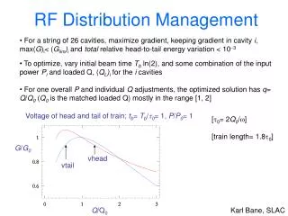
Gas Distribution System for Micromegas Detectors of New Small Wheel • 16 gas channels should provide gas mixture to each NSW. • •Each channel provide gas either to two LM wedges or to two SM wedges. • •The gas inlet comes from the outer rim and the gas outlet goes to the outer rim. G. Koutelieris
Gas Distribution SystemLM wedges • The total flow rate of the gas channel can be adjusted via a Flow Control Regulator (FCR). • •The impedances are interposed in each wedge inlet and specify the desire of the flow rate. • •By this way the gas is shared equally to each LM wedge (LM1+LM2 in series). G. Koutelieris
Gas Distribution SystemSM wedges • The same configuration is applied in the SM1+SM2 wedges, but with a different flow rate level. G. Koutelieris
3D Visualization of a gas channel G. Koutelieris
Design of new impedances for 4 renewals/day • LM Wedge • Q=10.44 L/h • Dch=500 ± 5 μm, Lch=10.30 mm • ZLM-500-10300-50-Q10 • SM Wedge • Q=6.84 L/h • Dch=450 ± 5 μm, Lch=12.71 mm • ZSM-450-12710-50-Q10 G. Koutelieris
Proposed methods for the Gas Leak Test • The production of the Micromegas modules (MM) for the New Small Wheel (NSW) upgrade phase I of the ATLAS muon spectrometer includes quality checking. • The gas tightness test is one of the essential quality checks. • The following two alternative methods has been proposed and should be used: 1)The Pressure Decay Rate (PDR) method. 2)The Flow Rate Loss (FRL) method. G. Koutelieris
The NSW requirements for the MM Modules The Acceptance Limit for any MM Module (M) or Multiplet (MP) is defined by QL,LIM=Vx10-5 L/min=1.67x10-7xV st. L/s. This limit is the functional one, while the leak rate of a typical ,well-made Module, has to be studied. With st. L/h we mean: Standard Ambient Temperature & Pressure (SATM, T=25 oC , P=1.01325 bar) How to correlate and under which conditions (st. L/s) with (bar∙L/s) in leak rate specifications ? Measured by direct method (e.g. FRL) in st. L/s Measured by indirect method (e.g. PDR) in bar∙ L/s G. Koutelieris
Proposed methods for the Gas Leak Test G. Koutelieris
The PDR Method • The main idea is to measure experimentally the pressure decay rate and then to calculate the gas flow rate. • Two theoretical models are consider i) the flow rate is a linear function of pressure (for laminar flows like viscous leak channels). ii) the flow rate is a function of pressure in the n-th power (n=0.5 is met in turbulent flow cases of viscous leak channels or orifices). We also are planning to use a mixed theoretical model. G. Koutelieris
The PDR Method • The data analysis is based on the best fit of the previous models. • During a gas leak test by the PDR method, a temperature variation is unavoidable. Its variation affects the pressure drop, causing incorrect determination of the leak rate without a kind of compensation. G. Koutelieris
The PDR method In this method the pressure drop in a pressurized chamber is measured within a specified time interval with respect to a perfectly tight reference chamber. The temperature variations in the chambers has to be reduced at start and stop states. usually expressed in bar.L/s Where V is the volume of the chamber, Pοthe initial pressure in the chamber, (ΔP) is the pressure drop in the chamber with respect to the pressure of the reference chamber and (ΔP)corr , a correction term due to temperature variation and Δt the time interval. G. Koutelieris
The FRL method • Method based on flow rate loss (FRL) • In this method the gas Flow Rate Loss through a chamber is measured for several flow • rate levels, preferably much higher than the nominal one, by using two mass flow sensors. (could be expressed in L/s ) Where Qin(n) is the flow rate in the input, Qout(n) is the flow rate in the output at nth measurement and N is the total number of measurements. B MFS1 MFS2 Qin Qout A In horizontal position G. Koutelieris
Advantages of the FRL method • Insensible in the temperature and atmospheric pressure variations. • It can speed up the measurements the gas leak test because it lasts few minutes (after the steady state flow). • Its sensitivity can be increased not in expense of lasting time (e.g. using advanced techniques like the Lock-In Amplifier). G. Koutelieris
The prototype setup for combined use of the PDR and the FRL methods. MFS: mass flow sensor DM: differential manometer DVM: digital voltmeter FCR: flow control regulator V: valve CN: calibrated needle G. Koutelieris
Emulated leaks by using medical needles • The investigation of the detection limit of our setup was feasible by using medical (hypodermic) needles of the series 27G, 28G/29G, 30G, 31G, 32G and 34G (difficult to find as few samples). • The needles are inserted in the side of a plastic pipe. By this technique we accomplished excellent tightness and at the same time predicted results. G. Koutelieris
LIA technique: the method In LIA technique, the signal with a superimposed noise and the internal lock-in signal are multiplied (synchronous demodulation). The principle of the method is based on the orthogonality property. and an internally generated: Let us a sinusoidal signal: The produced Phase Sensitive Detector output signal (VPSD) contains a low frequency level component proportional to the signal amplitude: noise If and , then DC signal The DC component is obtained by using a low pass filter. G. Koutelieris
Baseline setup/stage-0 (overall configuration) Included only in the upgrade stage 1 G. Koutelieris
Data recording by the communication software • The LIA 5210 is supported by the ``Acquire Data Acquisition Software'‘, version 4.2. The device can be controlled remotely by this software while 4 ADC channels, having resolution 1 mV, are also available. • Using this software we recorded the variation of the differential signal VS obtained from CH1 out via the ADC1 input provided by the LIA 5210. VS at pressure p2 (p2>p1) VS at pressure p1 VS at pressure p1 stability≈0.3 % pressure ↑ pressure ↓ G. Koutelieris
A view of the setup being installed at BB5 at CERN • The installation of the Gas Tightness Station has been started in April. • It includes the instruments and components referring to that we call baseline (stage-0) setup. G. Koutelieris
Conclusions • The overall gas distribution system for MM Multiplets has been well specified . • The associated gas components have been discriminated (switch valves, impedances, manifolds, mass flow sensors). • Implementation of combined GLT methods, PDR and FRL, in a single prototype setup. Leak rates much lower than the NSW limits have been measured. • The proposed FRL method has been successfully tested and seems reliable, fast, accurate and insensible to the temperature variations. A data acquisition and control platform based on WinCC is on the way. • We started installing the baseline setup (stage-0) of the Gas Tightness Station at BB5 at CERN. As soon as the gas supply is ready we can proceed to functional tests. • The upgrade stage-1, based on the LIA technique, has been implemented at NTUA and could be introduced at BB5. G. Koutelieris