Download
1 / 66
660 likes | 827 Views
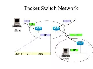
Packet Switch Network. IP. IP. IP. client. IP. IP. IP. IP. TCP. Data. Ether. Server. TCP/IP Layering. DHCP, Mail, WWW, TELNET, FTP. Application. Socket Library. TCP. UDP. Layer 4 / Transport. ARP. RARP. IP. ICMP. Layer 3 / Network. Ethernet. PPP. Layer 2 / Data Link.

E N D
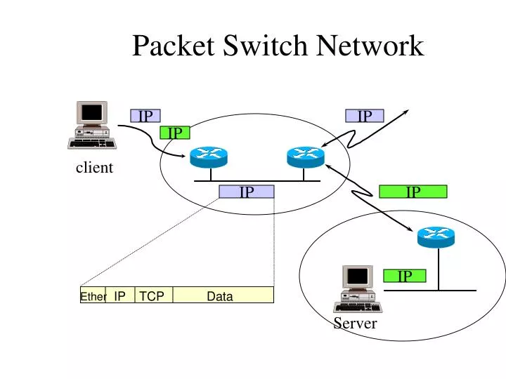
Packet Switch Network IP IP IP client IP IP IP IP TCP Data Ether Server
TCP/IP Layering DHCP, Mail, WWW, TELNET, FTP... Application Socket Library TCP UDP Layer 4 / Transport ARP RARP IP ICMP Layer 3 / Network Ethernet PPP Layer 2 / Data Link Network card Com Layer 1 / Physical
Demultiplexing application application application application ICMP IGMP TCP UDP ARP IP RARP Ethernet incoming frame
data CRC type 6 6 2 64-1500 4 dst src
IP Address 7 bits 24 bits Class A 0 netid hostid 0.1.0.0 to 126.0.0.0 14 bits 16 bits Class B 1 0 netid hostid 128.0.0.0 to 191.255.0.0 21 bits 8 bits Class C 1 1 0 netid hostid 192.0.1.0 to 223.255.255.0 28 bits Class D 1 1 1 0 multicast group ID 224.0.0.0 to 239.255.255.255
IP Address/Physical Address • Static Mapping • IP broadcast address maps to Ethernet broadcast address) • IP Multicast Address maps to Ethernet Multicast Address • lower 23bits of class D IP map into the lower 23bits of Ethernet address 01:00:5e:00:00:00 • Dynamic Mapping • ARP • RARP
ARP • Address Resolution Protocol • RFC-826 • Mapping between IP address and the physical address(such as MAC)
ARP/RARP Packet Format 0 16 31 proto type hard type HLEN op PLEN sender ethernet address sender ether addr sender IP addr target ether addr sender IP addr target ethernet address target IP address Hardware type = 1 : Ethernet Protocol type = 080016: IP address HLEN: hardware address length = 6 : Ethernet MAC address length PLEN: protocol address length = 4 : IP address length OP(operation): 1: ARP request, 2: ARP response, 3: RARP request, 4: RARP response
How it works ? To :140.113.25.6 ‚ ARP IP … ƒ Ethernet † (broadcast) „ Ethernet Ethernet ARP ARP IP 140.113.25.6
IP • Internet Protocol
IP UDP TCP ICMP IGMP IP ARP Ethernet PPP
IP • Internet Protocol • RFC-791 • Unreliable • Connectionless • Dispatch packet to upper protocol • Fragmentation & Assembly • Routing
Packet Format 0 15 16 31 total length TOS HLEN VERS identification fragment offset flag TTL protocol header checksum 20 bytes source IP address destination IP address options(if any) VERS = 4 : IPv4 Protocol HLEN: times of 32-bit, if no options, the HLEN = 5 total length : the total length of the IP datagram, so the data-length of this packet is total length - HLEN *4 TOS: type of service 0 1 2 3 4 5 6 7 precedence D T R unsed precedence: ranging from 0 through 7, indicate the importance of each datagram. allow the router to implement congestion control algorithm D: low delay requests T: high throughput R: high reliability
Packet format • Version : 4 • Header length : number of 32-bit words • TOS : 3-bit precedence, 4 TOS bits, 1 unused • Identification : uniquely identifies each datagram sent by host • flags : more fragments • fragment offset : offset from original datagram • TTL : time to live
TOS 1 2 3 4 5 6 7 0 D T R 0 Precedence 0 Bit 0-2: Precedence. Bit 3: 0 = Normal Delay, 1 = Low Delay. Bit 4: 0 = Normal Throughput, 1 = High Throughput. Bit 5: 0 = Normal Relibility, 1 = High Relibility. Bit 6-7: Reserved for Future Use. Precedence 111 - Network Control 011 - Flash 110 - Internetwork Control 010 - Immediate 101 - CRITIC/ECP 001 - Priority 100 - Flash Override 000 - Routine
Flags & Fragment • Flags : 3 bits 1 2 0 0 DF MF Bit 0: reserved, must be zero Bit 1: (DF) 0 = May Fragment, 1 = Don't Fragment. Bit 2: (MF) 0 = Last Fragment, 1 = More Fragments. • Fragment Offset: 13 bits • Unit : 8 octets (64 bits)
Protocol number • IPPROTO_ICMP 1 IPPROTO_IGMP 2 IPPROTO_GGP 3 IPPROTO_TCP 6 IPPROTO_PUP 12 IPPROTO_UDP 17 IPPROTO_IDP 22 IPPROTO_RSVP 46
Header Checksum • How to calculate ? • checksum field = 0 • sum of 16-bit words • checksum = 1’s complement of sum • How to verify ? • receiver calculate the checksum should be 0xffff (?, 0x0000)
Fragmentation • MTU:Maximum Transmission Unit • Ethernet : 1500 • FDDI : 4352 • IEEE 802.3/802.2 : 1492 • Path MTU • smallest MTU of any data link that packets traverse between the two hosts
Fragmentation Algorithm Notation: FO - Fragment Offset IHL - Internet Header Length DF - Don't Fragment flag MF - More Fragments flag TL - Total Length OFO - Old Fragment Offset OIHL - Old Internet Header Length OMF - Old More Fragments flag OTL - Old Total Length NFB - Number of Fragment Blocks MTU - Maximum Transmission Unit
Fragmentation Algorithm IF TL =< MTU THEN Submit this datagram to the next step in datagram processing ELSE IF DF = 1 THEN discard the datagram ELSE To produce the first fragment: (1) Copy the original internet header; (2) OIHL <- IHL; OTL <- TL; OFO <- FO; OMF <- MF; (3) NFB <- (MTU-IHL*4)/8; (4) Attach the first NFB*8 data octets; (5) Correct the header: MF <- 1; TL <- (IHL*4)+(NFB*8); Recompute Checksum; (6) Submit this fragment to the next step in datagram processing; the length of data field in the IP packet must be the times of eight
Fragmentation Algorithm To produce the second fragment: (7) Selectively copy the internet header (some options are not copied, see option definitions); (8) Append the remaining data; (9) Correct the header: IHL <- (((OIHL*4)-(length of options not copied))/4; TL <- OTL - NFB*8 - (OIHL-IHL)*4); //previous sent and options not copied FO <- OFO + NFB; MF <- OMF; Recompute Checksum; (10) Submit this fragment to the fragmentation test; DONE.
Internet datagram options • The IP OPTIONS field is variable length. • The PADDING field depends on the options selected. • The IP OPTIONS field is used for testing or debugging. • Each option consists of a single octet option code, which may be followed by a single octet length and a set of data octets for the option. COPY bit 1: the option should be copied into all fragments. 0 : the option should only be copied into the first fragment and not into all fragments.
Record Route Option • The RECORD ROUTE OPTION allows the source to create an empty list of IP addresses and arrange for each router that handles the datagram to add its IP address to the list.
CODE field = 7 means option class = 0, option number = 7 for record route • LENGTH field specifies the total length of the option as it appears in the IP datagram, including the first three octets. • The POINTER field specifies the offset within the option of the next available slot. • If the pointer is greater than the length, the list is full, so the machine forwards the datagram without inserting its entry. It the list is not full, the machine inserts its 4-octet IP address at the position specified by the POINTER, and increments the POINTER by four.
source Route Options • It provides a way for the sender to dictate a path through the internet. • IP supports two forms of source routing. One form, called strict source routing, specifies a routing path by including a sequence of IP addresses in the option
strict source routing means that the addresses specify the exact path the datagram must follow to reach its destination. The path between two succcessive addresses in the list must consist of a single physical network; an error results if a router cannot follow a strict source route. • The other form, called loose source routing, also includes a sequence of IP addresses. It specifies that the datagram must follow the sequence of IP addresses, but allows multiple network hops between successive addresses on the list.
Timestamp Option • The timestamp option works like the record route option • Timestamps give the time and date at which a router handles the datagram expressed as milliseconds since midnight, Universal Time.
IP routing routing daemon route command netstat command UDP TCP yes Destination? no routing table IP output input queue
Routing Principles RouteDatagram(Datagram, RoutingTable) extract destination IP address, D, from the datagram and compute the network prefix, N; If N matches any directly connected network address deliver datagram to destination D over that network else if the table contains a host-specific route for D send data gram to next-hop specified in table else if the table contains a route for network N send datagrram to next-hop specified in table else if the table contains a default route send datagram to the default router specified in table else declare a routing error;
Simple Routing Table • netstat -rn Destination Gateway Flags Refcnt Use Interface 140.252.13.65 140.252.13.35 UGH 0 0 emd0 127.0.0.1 127.0.0.1 UH 1 0 lo0 default 140.252.13.33 UG 0 0 emd0 140.252.13.32 140.252.13.34 U 4 25043 emd0