Download
1 / 8
80 likes | 188 Views
Briefing: Independent NASA Test of RTSX-SU FPGAs Timing Analysis for MEC Tiger Team Results. Rich Katz, Grunt Engineer NASA Office of Logic Design. Basic Timing. n logic levels. 1 Clock Period. Ideal CLK. t PD. Basic Timing Analysis. Race of propagation delays vs. clock period

E N D
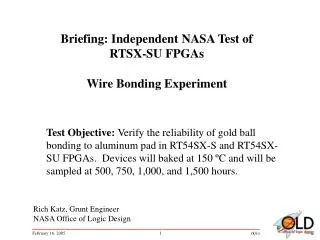
Briefing: Independent NASA Test of RTSX-SU FPGAsTiming Analysis for MEC Tiger Team Results Rich Katz, Grunt Engineer NASA Office of Logic Design
Basic Timing n logic levels 1 Clock Period Ideal CLK tPD
Basic Timing Analysis • Race of propagation delays vs. clock period • FF1: CLK Q • G1: tPD1 • G2: tPD2 • … • GN: tPDN • FF2: tSU • Slack = Period - (FF1 + G1 + … + GN + FF2) Sum of the delays
Basic Timing Analysis For a “real design,” there are hundreds or thousands of “slack” calculations. Put together, they form a distribution. For a single clock there are typically a few paths that limit performance of the ATE tester. This assumes that all paths are neither multi-cycle or propagate from one edge to the opposite one. Depending on the clock frequency and distribution of slack over the design, many timing faults are not detectable. The excess delay from damage can “hide in the timing slack.” 1 Clock Period Ideal CLK tPD Slack Slack Slack
Basic Timing AnalysisTiger Team Test Vehicle • Flip-flops are hooked together in a shift register configuration • Single clock • All on the same edge • N = 0 (no gate delays between flip-flops) • Slack ~ 15 ns • ATE limited to 50 MHz (20 ns) • Delta (increase) tPD≤ ~ 15 ns are not observable