Download
1 / 16
160 likes | 380 Views
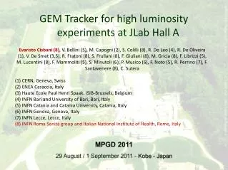
Status of the APV25 electronics for the GEM tracker at JLab. Evaristo Cisbani - INFN/Rome & Italian National Institute of Health On behalf of: Paolo Musico, Saverio Minutoli, Giuseppe Gariano - INFN/GE Freiburg 25/May/10 WG5-RD51 Collaboration Meeting. New SBS Spectrometer @ JLab.

E N D
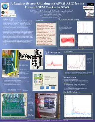
Status of the APV25 electronics for the GEM tracker at JLab Evaristo Cisbani - INFN/Rome & Italian National Institute of Health On behalf of: Paolo Musico, Saverio Minutoli, Giuseppe Gariano - INFN/GE Freiburg 25/May/10 WG5-RD51 Collaboration Meeting Cisbani-Musico-Minutoli / Status JLab Electronics
New SBS Spectrometer @ JLab • High Luminosity: 1038 /cm2/s • Support high background:500 kHz/cm2 (low energy photons mainly) • Forward angle • Large acceptance • Good angular and momentum resolutions:0.2 mrad, 0.5% @ 4-8 GeV/c • Flexibility:use the same detectors in different experimental setup hallaweb.jlab.org/12GeV/SuperBigBite/ Cisbani-Musico-Minutoli / Status JLab Electronics • Two tracker geometries: • front tracker • second and third tracker • will use the same “base module” GEP5 setup
Front Tracker Geometry X(4+4) Back Trackers Geometry SBS Tracker Chambers configuration GEp(5) SBS x6 • Modules are composed to form larger chambers with different sizes • Electronics along the borders and behind the frame (at 90°) – cyan and blue in drawing • Aluminum support frame around the chamber (cyan in drawing); dedicated to each chamber configuration Cisbani-Musico-Minutoli / Status JLab Electronics
GEM Trackers Accounting Cisbani-Musico-Minutoli / Status JLab Electronics Total chs. 101700 Last 2 FT modules with strips split in the middle (double segmentation on each site) ST and TT readout groups 4 strips in GEp(5) with binary readout
2D Readout Plane and ZIF extension • Readout along all sides • not strictly required in x/y unless additional segmentation of the readout plane • weight balance • unavoidable in diagonal u/v • Extension feeds into ZIF connectors: • no soldering on the readout foil • permit safer bending • Small frame width (8 mm); minimize dead area • Require precise cutting around the ZIF terminals x/y Cisbani-Musico-Minutoli / Status JLab Electronics Rui De Oliveira final design based on our drawing In production (almost done)
2D Readout Electronics Components GEMFECADC+VME Controller DAQ 8 mm Up to 10m FOTO MODULO VME 49.5 mm 75 mm Cisbani-Musico-Minutoli / Status JLab Electronics • Main features: • Use analog readout APV25 chips • 2 active components: Front-End card and VME64x custom module • Copper cables between front-end and VME Thanks to Michael Böhmer and Igor Konorov from TUM for very productive discussions on the design of the APV25 based FrontEnd card
Front End Card (Proto 0) GEMFECADC+VME Controller DAQ Front End card based on the APV25 chip 1 FE = 1 APV25 = 128 chs Panasonic FPC connectors Analog Driver Thermometer Analog Output Input Protection diodes Cisbani-Musico-Minutoli / Status JLab Electronics Digital IN Power Line I2C APV25 bonding on PCB Voltage regulators
Front-end prototypes tests • Front-end card under control • First tests on analog cable length positive • No analog driver 7 m cable Cisbani-Musico-Minutoli / Status JLab Electronics Work is in progress 50 cm cable
Front-End new version (Proto 1) • Bug fixing of previous version • Denser Bonding: 50 um pad, 100 um pitch • Backplane connector(back side) • 5 mm shorter • Under production Cisbani-Musico-Minutoli / Status JLab Electronics
Front-End adapter card (for testing) • LEMO/TTL to Differential • Differential Analog to Differential LEMO • USB to I2C • Single 3.3 V power line • Very simple but useful Cisbani-Musico-Minutoli / Status JLab Electronics
Electronic layout on one chamber D C A B Cards and modules are supported by an outer carbon-fiber frame which runs all around the chamber. Optimization is in progress. Cisbani-Musico-Minutoli / Status JLab Electronics
FE –Backplane- VME • Next release will use a rigid PCB backplane for analog and digital lines (keep the cable option for testing • Backplane is the mechanical supports for the vertical cards in between two GEM modules • Controlledimpedance Cisbani-Musico-Minutoli / Status JLab Electronics
Single chamber cabling layout • Use HDMI connectors and cables from Backplanes from/to VME • HDMI-A for digital lines (4+1 differential lines) • HDMI-B for analog lines (7+1 differential lines) • Patch panel must regroup channels in order to have digital and analog from/to the same VME module • Green: digital / Red: analog • Total length (digital+analog) constant • 2x(4+5+5) 2 VME + 2x(4+4+5) 2 VME Cisbani-Musico-Minutoli / Status JLab Electronics
VME64x Controller Flash EPROM • VME controller hosts the digitization of the analog signals coming from the front-end card. • It handle all control signals required by the front end cards (up to 16 FE) • Compliant to the new JLab/12 VME64x VITA 41 (VXS) standard • We intend to make it accessible by standard VME as well • Modular design: with the possibility to easily detach the analog module to extend FEC-VME64x distance • Under TEST Optical Fiber Oscillators (100 MHz, 62.5 MHz) Thermometer ETH Live Insertion Hot-Swap USB 2x64Mbyte SDRAM • From the VXS backplane: • Trigger L1/L2 • Synch • Clock • Busy (OUT) • (duplicated on front panel) Voltage Regulators for each module Cisbani-Musico-Minutoli / Status JLab Electronics Digital OUT ADCs 50 MHz 12 bits Analog Receivers 16 Analog IN
VME64x Controller / ALTERA Firmware • Firmware on Verilog (under test): • VME-32 bit interface (64-bit interface very preliminary) • USB-interface (VME and USB share the same resources) • PLL configuration interface (APV-ADC clock phasing) • I2C master interface • Trigger handler (very simple) via front panel LEMO • ADC serial configuration interface and de-serializer • APV25 frame decoder; value stored on a FIFO accessible from VME and USB. • Single channel histogram (useful for delay tuning ...) • Front end test signals generator Cisbani-Musico-Minutoli / Status JLab Electronics
Conclusions • Front-end card prototype 0: tested, bug fixed and improvement defined • Front-end card prototype 1: under production • VME-controller prototype 0: • everything mounted except VME transceivers • most of the firmware modules implemented • under heavy test • Expect to install in GEM module (40x50cm2) end of June – test in July • Usable system expected September/2010 Cisbani-Musico-Minutoli / Status JLab Electronics