Download
1 / 18
180 likes | 184 Views
This document outlines the participating institutions, technical description and requirements, status, organization and WBS responsibilities, schedule, milestones, cost summary, and key issues and concerns of the LAT Calorimeter Subsystem.

E N D
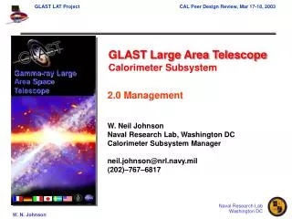
LAT Calorimeter Subsystem W. Neil Johnson Calorimeter Subsystem Manager Paolo Carosso Calorimeter Project Manager Space Science Division Naval Research Laboratory johnson@gamma.nrl.navy.mil
LAT Calorimeter Subsystem Outline • Participating Institutions • Technical Description and Requirements • Status • Organization and WBS responsibilities • Schedule • Milestones • Cost Summary • Key Issues and Concerns
Calorimeter Hardware Team • Naval Research Laboratory (NRL), Washington DC • Overall scientific and management lead • System engineering & performance assurance • Electronics • Software • Integration, test, and calibration • Stanford Linear Accelerator Center (SLAC), Stanford, CA • ASIC design and development • Electronics oversight • Commissariat à l'Energie Atomique / Direction des Sciences de la Matière, Département d'Astrophysique, de Physique des Particules, de Physique Nucléaire et de l'Instrumentation Associée (CEA/DSM/DAPNIA), Saclay, France • Management, France • PIN Photodiodes • LAT Power Supplies • Centre National de la Recherche Scientifique / Institut National de Physique Nucléaire et de Physique des Particules (IN2P3) – 3 Laboratories • LPNHE, Ecole Polytechnique - Lead, mechanical structure & optical performance, assembly and test • PCC, Collège de France - CsI detector elements, Simulations, Software • CENBG of Université de Bordeaux - ASIC Test Bench, Beam Test support and analyses • Royal Institute of Technology (KTH) and Stockholm University in Stockholm, Sweden • CsI Crystals and acceptance testing
Large Area Telescope (LAT) Design Overview Instrument 16 towers modularity height/width = 0.4 large field-of-view Si-strip detectors: 228 mm pitch, total of 8.8 x 10⁵ ch. hodoscopic CsI crystal array cosmic-ray rejection shower leakage correction XTkr + Cal = 10 X0 shower max contained < 100 GeV segmented plastic scintillator minimize self-veto > 0.9997 efficiency & redundant readout Tracker Calorimeter Anticoincidence Detector Shield 3000 kg, 650 W (allocation) 1.75 m 1.75 m 1.0 m 20 MeV – 300 GeV
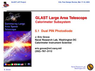
Each Module 8 layers of 12 CsI(Tl) Crystals Crystal dimensions: 27 x 20 x 336 mm Hodoscopic stacking - alternating orthogonal layers Dual PIN photodiode on each end of crystals. Mechanical packaging – Carbon Composite cell structure Electronics boards attached to each side. Electronic readout to connectors at base of calorimeter. Outer wall is EMI shield and provides structural stiffness as well. Calorimeter Module Concept Modular Design 4 x 4 array of calorimeter modules
Calorimeter Technical Challenges • Imaging calorimetry to support background rejection and improve energy measurement via shower profile correction or leakage estimation. • Hodoscopic arrangement of CsI crystals, 8 layers of 12 crystals • Longitudinal positioning in individual crystals using light asymmetry measurements at each end of crystal • Large dynamic range ( ~5 x 10⁵) with low power electronics • Divide signal into two ranges using dual PIN Photodiode of differing areas • Custom CMOS ASIC front end electronics • Minimize passive material and gaps in active material caused by modular design, yet survive 7g launch loads. • Carbon composite structure with individual cells for each CsI crystal. • PIN diode readout via PCB on four sides of module. • EMI/structural outer wall. • Low dead time (< 20 usec), low power spectral measurements over full energy range. • Dedicated ADC for each CsI crystal end • COTS low-power successive approximation ADCs • In-flight calibration • Use cosmic rays (p – Fe)
Calorimeter Design Status • Full scale prototype designed and fabricated as part of NASA Advanced Technology Development (ATD) Program • Tested in SLAC Beam Test, Dec 1999 – Jan 2000 • Tested in GSI Beam Test (C, Ni beams), July 2000 • Refurbished for Suborbital flight, planned June 2001 • Current design builds on ATD prototype with significant changes: • Mechanical design is based on carbon composite cell structure proposed by IN2P3, based on CMS concepts and experience • Electronics designs and interfaces have been modified to reflect the LAT-wide trigger and data flow concepts and communications protocols • Design and fabrication responsibilities were redistributed to include major contributions from collaborators in France and Sweden • As a result • The optical and mechanical performance characteristics of the new mechanical packaging concept are in progress • The analog front end ASIC design was delayed for two years. The work has recently been transferred from France to SLAC. • Restructuring of the responsibilities and the French management requires a re-definition of the baseline schedule and costs.
Design Status (cont) • Mechanical Structure • Prototype fabricated and populated with dummy crystals for vibration testing. Vibration testing complete. • Optical properties of structure coating and possible crystal wrappings have been studied. • Crystal Detector Elements • CsI Crystal procurement has been advertised, 3 bids have been received for 1st crystals delivered by May ’01. • PIN Photodiode specification is complete for engineering model prototype diodes. • Light yield studies completed for various wrapping materials. • PIN diode bonding tests – epoxies and silicone elastomers have been tested. • Baseline design uses silicone elastomer bond stabilized by external frame that is epoxied to CsI crystal – tests beginning. • Electronics • Test structures for analog front end ASIC are under test. • 1st submission of fully functional ASIC scheduled for March. • Radiation testing (SEU, SEL) of COTS ADCs has identified two potential ADCs.
Calorimeter Module Assembly 18 Identical Calorimeter Modules: • 2 Calibration Units (Flt spares) • 16 Flight Units
Schedule Milestones • Calorimeter (CAL) Requirements Review 03/14/01 • Interim Subsystem Review 02/28/01 • Interim Subsystem Review 06/29/01 • Calorimeter PDR 07/11/01 • LAT Instrument PDR 08/06/01 • Engineering Model (EM) assembly complete 04/01/02 • Calorimeter CDR 06/05/02 • EM Test complete 06/28/02 • LAT Instrument CDR 08/05/02 • Qual Modules A & B Ready for Integration (calibration unit) 05/15/03 • Flight Modules 1 & 2 Ready forIntegration (calibration unit) 08/01/03 • Flight Modules 3 – 16 Ready forIntegration 10/01/03 – 12/24/03
Interim Calorimeter Cost Estimate* (Escalated K$) *DOE/NASA funding.
Issues • Delays in committing to and implementing MoA and International Agreement are impacting schedule • NASA now moving forward with International Agreement (CNES); MoA is ready for signature; CAL Implementation Plan being developed • Hardware responsibilities have been re-allocated and French management and staffing is underway • Frequency of technical exchange to increase: series of face-to-face meetings scheduled and committed to; focus on finalizing Implementation Plan • Establishing baseline performance by PDR • Accelerated fabrication and testing of prototype PEM structure • Accelerated PIN diode specification and prototype procurement • Optical bond of PIN diode to CsI crystals • Issue is degradation of optical quality of bond through temperature cycling • Hard epoxies have failed – LAT prototype and ESA’s Integral Pixit instrument • Aggressively investigating silicone elastomeric pads and soft epoxy solutions • Qualification of COTS ADC • Speed and power requirements essentially require COTS (commercial off the shelf) successive approximation CMOS ADCs. • Testing 5 different COTS parts from Burr Brown and Maxim. SEL measurements on two Maxim parts are encouraging • SEU testing at Brookhaven will occur in March. • Fabrication, test, calibration and delivery schedule for 16 flight modules. • Delivery rate represents schedule risk; will work closely with LAT IPO to optimize overall schedule