Download
1 / 59
600 likes | 628 Views
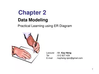
UNIT I ER Diagram. Information Management. Data Modeling is an Analysis Activity. Project Identification and Selection. Purpose –thorough analysis Deliverable – functional system specifications. Project Initiation and Planning. Analysis. Logical Design. Physical Design.

E N D
UNIT I ER Diagram Information Management
Data Modeling is an Analysis Activity Project Identification and Selection Purpose –thorough analysis Deliverable – functional system specifications Project Initiation and Planning Analysis Logical Design Physical Design Database activity – conceptual data modeling Implementation Maintenance
The Entity-Relationship Model • Introduction • Business Rules • Sample E-R Diagram • Basic E-R Notation • E-R Model Constructs: Entity Type • E-R Model Constructs: Attributes • E-R Model Constructs: Identifier • E-R Model Constructs: Relationships • E-R Model Constructs: Cardinality
Business Rules • Statements that define or constrain some aspect of the business • Assert business structure • Control/influence business behavior • Expressed in terms familiar to end users • Automated through DBMS software • Example: • “A student may register for a section of a course only if he or she has successfully completed the prerequisites for that course.”
A Good Business Rule is: • Declarative – what, not how • Precise – clear, agreed-upon meaning • Atomic – one statement • Consistent – internally and externally • Expressible – structured, natural language • Distinct – non-redundant • Business-oriented – understood by business people
E-R Model Constructs • Entity instance - person, place, object, event, concept (often corresponds to a row in a table) • Entity Type – collection of entities (often corresponds to a table) • Attribute - property or characteristic of an entity type (often corresponds to a field in a table) • Relationship instance – link between entities (corresponds to primary key-foreign key equivalencies in related tables) • Relationship type – category of relationship…link between entity types
Basic E-R Notation A special entity that is also a relationship Entity symbols Attribute symbols Relationship symbols
E-R Model Constructs: Entity Type • Entity - person, place, object, event, concept • Entity Type versus Entity Instance • Entity type: a collection of entities that share common properties or characteristics • Entity instance: a single occurrence of an entity type • Entity Type versus System Input, Output, or User • Treasurer is the person entering data. • “Gives-to” and “Summarizes” are business activities, not relationships between entities. • Inappropriate Entities
What Should an Entity Be? • SHOULD BE: • An object that will have many instances in the database • An object that will be composed of multiple attributes • An object that we are trying to model • SHOULD NOT BE: • A user of the database system • An output of the database system (e.g. a report)
E-R model with inappropriate entities System output System user E-R model with only the necessary entities
A strong entity type is an entity that exists independently of other entity types Identifying owner Identifying relationship A weak entity type is an entity type whose existence depends on some other entity type Weak entity identifier is its partial identifier combined with that of its owner An Example E-R Model ConstructsStrong vs Weak Entity Type
E-R Model Constructs: Attributes • Attribute: a property or characteristic of an entity type that is of interest to the organization • Simple versus Composite Attribute • a simple attribute cannot be broken down into smaller components, while a composite attribute can be broken down into component parts • Single-Valued versus Multivalued Attribute • Stored versus Derived Attributes • A stored attribute is one whose values are stored in the database • A derived attribute is one whose whose values can be calculated from related stored attributes
A composite attribute An attribute broken into component parts
Entity with a multivalued attribute (Skill) and derived attribute (Years_Employed) Multivalued: an employee can have more than one skill Derived from date employed and current date
Figure 3-19 – an attribute that is both multivalued and composite This is an example of time-stamping
E-R Model Constructs: Identifier or Key • Identifier or Key • an attribute (or combination of attributes) that uniquely identifies individual instances of an entity type • Simple Key versus Composite Key • Candidate Key - an attribute that could be a key • Criteria for Selecting Identifiers • Will not change in value • Will not be null • No intelligent identifiers (containing e.g. locations or people that might change) • Substitute new, simple keys for long, composite keys
The key is underlined Simple key attribute
The key is composed of two subparts Composite key attribute
Relationships • Relationship type (is a meaningful association between entity types; is modeled as the diamond and lines between entity types; can have attributes) vs. Instance • Multiple Relationships • more than one type of relationship between entities • Degree of a relationship - number of entity types that participate in it • Unary (or Recursive) Relationship • Binary Relationship • Ternary Relationship • Cardinality of Relationships • Many-to-Many and Associative Entities (combination of relationship and entity) • All relationships involved are “many” • Result has independent meaning • One or more non-key attributes
One entity related to another of the same entity type Entities of two different types related to each other Entities of three different types related to each other Degree of relationships – from figure 3-2
Cardinality of Relationships • One – to – One • Each entity in the relationship will have exactly one related entity • One – to – Many • An entity on one side of the relationship can have many related entities, but an entity on the other side will have a maximum of one related entity • Many – to – Many • Entities on both sides of the relationship can have many related entities on the other side
An associative entity (a) Attribute on a relationship
Relationships: Cardinality • Cardinality Constraints - the number of instances of one entity that can or must be associated with each instance of another entity • Minimum Cardinality • If zero, then optional • Maximum Cardinality • Mandatory One - when min & max both = 1
Introducing cardinality constraints Basic relationship
Examples of cardinality constraints Mandatory cardinalities
Relationships: Time Stamping • Modeling Time-Dependent Data
Pine Valley Furniture product database (a) E-R diagram not recognizing product reassignment
Two user views for Pine Valley Furniture (a) User View 1: Orders for customers
Cardinality Constraints • Cardinality Constraints - the number of instances of one entity that can or must be associated with each instance of another entity. • Minimum Cardinality • If zero, then optional • If one or more, then mandatory • Maximum Cardinality • The maximum number
Ternary relationships Note: a relationship can have attributes of its own
Basic relationship with only maximum cardinalities showing Mandatory minimum cardinalities
Optional cardinalities with unary degree, one-to-one relationship
A binary relationship with an attribute Here, the date completed attribute pertains specifically to the employee’s completion of a course…it is an attribute of the relationship
A unary relationship with an attribute. This has a many-to-many relationship Representing a bill-of -materials structure
Examples of multiple relationships – entities can be related to one another in more than one way