Download
1 / 38
480 likes | 632 Views
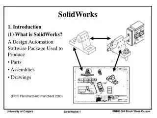
SolidWorks Features. Ferdowsi University of Mashhad Dr. Behnam Moetakef Imani. Features: Dome. Dome create one or more dome features simultaneously on the same model Distance . Reverse Direction . Constraint Point or Sketch Direction . Elliptical dome . Continuous dome.

E N D
SolidWorks Features Ferdowsi University of Mashhad Dr. Behnam Moetakef Imani
Features: Dome • Dome • create one or more dome features simultaneously on the same model • Distance. • Reverse Direction . • Constraint Point or Sketch • Direction. • Elliptical dome. • Continuous dome.
Constraint Point or Sketch: • Control the dome feature by selecting a sketch that contains points to constrain the shape of the sketch. • When you use a sketch containing points as a constraint, the Distance is disabled.
Dome Examples • elliptical dome for cylindrical or conical models: • An elliptical dome's shape is a half ellipsoid, with a height equal to one of the ellipsoid radii.
Dome Examples • continuous dome for polygonal models: • continuous dome's shape slopes upwards, evenly on all sides. • Not checked, the shape rises normal to the edges of the polygon
Example of Shape Constraints Features: Shape • Creates a deformed surface on a model by: • expanding, • constraining, • and tightening the selected surface. • A deformed surface is flexible, much like a membrane.
Features: Deform • deform feature alters shapes of complex surface or solid models, • either in a local area or globally, • without concern for the sketches or feature constraints used to create the models. • deform feature can be appied to both SolidWorks and imported models. • There are three deform types: • Point • Curve to curve • Surface push
Deform - Curve • Using the Curve to curve deform option
Deform - Surface Push • Surface push deform modifies surfaces of target bodies by pushing tool bodies into them. • You select a customizable pre-built tool body, • such as a polygon or sphere, or • use your own tool bodies • triad callout in the graphics area to size the tool body • surface push deform approximates the surfaces of the tool bodies • while maintaining the identities of the surfaces of the target bodies (the number of faces, edges, and vertices remains unchanged in the final target body) • design free-form surfaces, tooling, plastics, soft packaging, sheet metal, and other applications where it is useful to incorporate the characteristics of tool bodies into existing designs
Deform - Surface Push • you must have the body of the part that you are modeling, and a tool body that you will use to shape the part that you are modeling. • The finished shape does not fit the tool body directly, but looks about half-way between the model and the tool body, blended together in an abstract sort of way. • It looks like the dent that would result from an object being thrown very hard at a car fender, in that neither the thrown part nor the fender is immediately recognizable from the result.
Wrap feature • enables you to wrap 2D sketches around cylindrical and conical faces • point of the cone must be cut off • The reason why it is limited to cylindrical and conical faces is that these types of geometry are developable. • Developable geometry can be flattened without stretching.
Wrap feature Wrap feature has three main options: • Emboss • Deboss • Scribe
Wrap feature • One result is that creating a full wrap-around feature, such as the geometry for a drum cam, requires a secondary feature. • This is because the Wrap feature always leaves a gap, regardless of whether the sketch to be wrapped is under or over the diameter-multiplied-by-pi length. • you can use a loft, extrude, or revolve feature to span the gap.
Wrap feature • When you use the Emboss option, you can set up the direction of pull and assign draft so that the feature can be injection molded. • This limits the size of the emboss so that it must not wrap more than 180 degrees around the part.
Flex feature • The Flex feature is different from most other features in SolidWorks. • Most other features create new geometry, but Flex (and Deform) takes existing geometry and changes its shape. • Flex can affect the entire part, or just a portion of it. • Flex works on both solid and surface bodies, as well as imported and native geometry.
Flex feature Flex has four main options and various settings. • Bending. Establishes two trim planes to denote the ends of the bent area, and specifies an angle or radius for the bend. • Twisting. Establishes two trim planes to limit the area of the twist, and enters degrees through which to twist. • Tapering. Establishes two trim planes to limit the area of the taper. The body will be larger toward one end and smaller toward the other end. • Stretching. Establishes two trim planes to limit the area to be stretched. You can stretch the entire body by moving the trim planes outside of the body.
Flex feature • Bending. Establishes two trim planes to denote the ends of the bent area, and specifies an angle or radius for the bend.
Flex feature • Twisting. Establishes two trim planes to limit the area of the twist, and enters degrees through which to twist
Flex feature • Tapering. Establishes two trim planes to limit the area of the taper. The body will be larger toward one end and smaller toward the other end.
Indent feature • Indent feature • The indent feature creates an offset pocket or protrusion feature on a target body that exactly matches the contour of a selected tool body, using thickness and clearance values to create the feature. • Depending on the body type selected (solid or surface), you specify the clearance between the target body and the tool body, and a thickness for the indent feature. • The indent feature can deform or cut material from the target body
Indent feature • The indent feature uses the form of the tool body to create a pocket or protrusion in the target body, so more faces, edges, and vertices appear in the final body than in the original body. This differs from the deform feature, where the number of faces, edges, and vertices remains unchanged in the final body. • Indent is useful in many applications where complex offsets with specific thickness and clearance values are required. Some examples include packaging, stamping, molds, press fits for machinery, and so on.
Indent feature • For example, building a plastic housing around a small electric motor, then the Indent feature shapes the housing and creates a gap between the housing and the motor
Freeform feature • Freeform feature will be covered in Surface presentation.
تمرین • تمرین • با استفاده از دستور wrap یک بادامک استوانه ای طراحی کنید. برنامه حرکت را از طریق curve through free points وارد نمایید. نوع حرکت rise:3-4-5 و return:cycloid می باشد. • با استفاده از دستور flex بطری آب واتا را مدل کنید.
تمرین 3) با استفاده از دستور indent برای مته ای که طراحی کرده اید یک cover ایجاد نمایید.