Download
1 / 17
270 likes | 395 Views
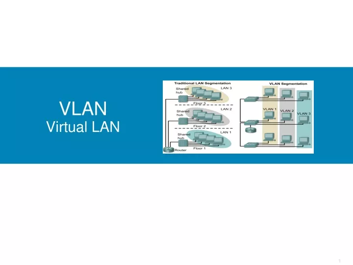
VLAN Virtual LAN. Definisi VLAN. Pemisahan jaringan secara logis yang dilakukan pada switch Pada tradisional switch, dalam satu switch menunjukkan satu segmentasi LAN dengan satu broadcast domain

E N D
Definisi VLAN • Pemisahan jaringan secara logis yang dilakukan pada switch • Pada tradisional switch, dalam satu switch menunjukkan satu segmentasi LAN dengan satu broadcast domain • Dengan adanya VLAN dimungkinkan satu switch bisa dibangun beberapa segmen jaringan dengan beberapa broadcast domain, dibentuk dengan bantuan software di switch • VLAN terbentuk secara logik dengan bantuan software yang ada pada switch
Manfaat VLAN 10.0.0.0/8 1) Without VLANs • Tanpa VLAN untuk membangun 3 jaringan membutuhkan 3 switch • Dengan menggunkan VLAN untuk membangun 3 jaringan hanya membutuhkan 1 switch 10.2.0.0/16 10.3.0.0/16 10.1.0.0/16 2) With VLANs 10.2.0.0/16 10.3.0.0/16
Without VLANs – No Broadcast Control ARP Request • Without VLANs, the ARP Request would be seen by all hosts. • Again, consuming unnecessary network bandwidth and host processing cycles.
With VLANs – Broadcast Control Switch Port: VLAN ID ARP Request
. VLAN operation Important notes on VLANs: • VLANs are assigned on the switch port. There is no “VLAN” assignment done on the host (usually). • In order for a host to be a part of that VLAN, it must be assigned an IP address that belongs to the proper subnet. Remember: VLAN = Subnet
. Creating VLANs • Untuk setipa switch bangun definisi VLAN S1(config)#vlan 10 S1(config-vlan)#name faculty/staff S1(config-vlan)#vlan 20 S1(config-vlan)#name student • KOnfigurasi masing-masing interface ke spesifik vlan Switch(config)#interface fastethernet 0/9 Switch(config-if)#switchport mode access Switch(config-if)#switchport access vlan 10 vlan 10 Default vlan 1 Default vlan 1
. Configuring Ranges of VLANs SydneySwitch(config)#interface fastethernet 0/5 SydneySwitch(config-if)#switchport access vlan 2 SydneySwitch(config-if)#exit SydneySwitch(config)#interface fastethernet 0/6 SydneySwitch(config-if)#switchport access vlan 2 SydneySwitch(config-if)#exit SydneySwitch(config)#interface fastethernet 0/7 SydneySwitch(config-if)#switchport access vlan 2 vlan 2
. Configuring Ranges of VLANs SydneySwitch(config)#interface range fastethernet 0/8, fastethernet 0/12 SydneySwitch(config-if)#switchport access vlan 3 SydneySwitch(config-if)#exit This command does not work on all 2900 switches, such as the 2900 Series XL. It does work on the 2950. vlan 3
. Verifying VLANs – show vlan vlan 1 default vlan 2 vlan 3
. Verifying VLANs – show vlan brief vlan 1 default vlan 2 vlan 3
. Deleting VLANs Switch(config-if)#noswitchport access vlan vlan_number
. VLAN Tagging • There are two major methods of frame tagging, Cisco proprietary Inter-Switch Link (ISL) and IEEE 802.1Q. • ISL used to be the most common, but is now being replaced by 802.1Q frame tagging. • Cisco recommends using 802.1Q. • VLAN Tagging and Trunking will be discussed in the next chapter. 802.10
VLAN Tagging • Terdapat satu VLAN yang berfungsi sebagai jalur komunikasi antar VLAN dan diset no IP • Terdapat satu interface yang difungsikan sebagai jalur komunikasi antar VLAN dan diset no IP
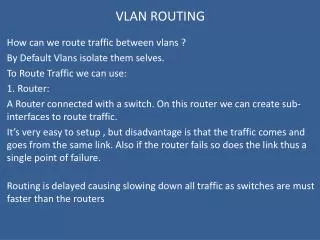
InterVLAN routing • Merupakan konsep VLAN tagging yang diterapkan di router • Pada Router, Dipersiapkan interface yang menerima komunikasi antar VLAN : • Dibangun sub interface untuk default gateway dan • sub interface untuk komunikasi antar VLAN , aktifkan mode trunk • Pada Switch Terdapat Switch sbg VTP Server • Bangun interface ke router, aktifkan mode trunk • Bangun Interface ke switch vtp client, aktifkan mode trunk Terdapat switch sbg VTP Client Bangun interface ke switch VTP Server activekan mode trunk
InterVLAN Routing • Pada Router