Download
1 / 20
200 likes | 210 Views
CMX Hardware Overview. Chip Brock, Dan Edmunds, Philippe Laurens@MSU Yuri Ermoline @CERN Wojciech Fedorko @UBC Michigan State University 12-May-2014. Common Merger eXtended module (CMX). Overall project CMX HW/FW/SW. Design Efforts in parallel on 5 fronts: MSU : CMX hardware

E N D
CMX Hardware Overview Chip Brock, Dan Edmunds, Philippe Laurens@MSU Yuri Ermoline@CERN Wojciech Fedorko @UBC Michigan State University 12-May-2014
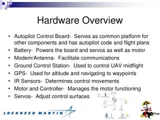
Overall project CMX HW/FW/SW • Design Efforts in parallel on 5 fronts: • MSU : CMX hardware • Raymond Brock, Dan Edmunds, Philippe Laurens • CERN : VAT card, BSPT FPGA firmware, CANbus tests • Yuri Ermoline • CERN : CMX software • DucBao Ta • UBC : BF FPGA firmware • WojtekFedorko • Stockholm : BF FPGA firmware, TP FPGA test firmware, JEM test firmware • PawelPlucinski
CMX is part of L1calo Phase 0 upgrade • CMX == L1Calo Trigger replacement for current Common Merger Module (CMM) • Phase-I accelerated item a.k.a. Phase-0
The CMX was designed to: • Perform all tasks currently handled by any CMM. • Extend these CMM tasks to higher input and output line rates. • Offer more computing power for additional thresholds or algorithms using the extended input • Provide an output to L1topo, sending a raw or processed copy of its inputs, optically at 6.4Gb. • Provide optional functionality to perform Topological Processing on CMX platform if needed.
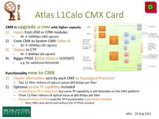
Definition: Base Function • Extended CMM functionality (Crate CMMs and System CMMs) • Receive and process 400 JEM/CPM input signals (@4x CMM rate) • All Crate CMXs send local summary to their System CMX through backplane connectors over LVDS cables (plan is @2x CMM rate) • System CMXs form and send triggering information to CTP over LVDS cables (plan is no change from CMM rate) • all CMXs send ROI and DAQ information over G-links (same as CMM) • Source of data for L1topo: send CMX inputs from JEMs or CPMs • Using 2x Avago miniPOD optical transmitters and 2x 12-fiber ribbons • Some level of duplication is required (originally 2x copies, now 4x) • One 12-fiber ribbon @6.4Gbps sufficientto send all raw input data • But plan is to send zero-suppressed data on 2,6 or 8x fibers per CMX optical patch panel is required
Definition: CMX-Topo Function • LimitedTopological Processing capabilityon CMX platform • Receive optical inputs from some/all of the 12x CMXs using 3x Avago receivers for up to 36x input fibers • Run multiple Topological Algorithms • Send Topological Triggering Information to CTP • Able to act as its own ROD for DAQ and ROI readout support both G-link and S-link • The CMX-Topofunctionality was requested as a backup plan in case L1topo could not be built, or if its availability had been delayed. • A CMX-Topo system will most likely not be used in L1calo • Somebody may devise an alternate and creative usage for the TP FPGA, or its role may remain limited to testing BF optical outputs in the test stand.
CMX Project Evolution • Preliminary Design Review Stockholm (June 2011) • Initial Specification • Design Study Technical Workshop @RAL (Feb 2012) with additional decisions: • Use 2x separate FPGAs: Base Function in BF FPGA and Topo Function in TP FPGA • Use Virtex 6 XC6VLX550T device for both • 2x 12-fiber outputs from BF FPGA to L1topo • 3x 12-fiber inputs to TP FPGA • Prototype Design Review (March 2013) corrected assumptions, added requirements: • Only 2x MTP feedthrough connectors • Allow Compact Flash card to be accessed through front-panel • Production CMXs with only BF FPGA only need 2x connectors • Use “octopus cables” if TP FPGA is present • CANbus also monitors power supply currents • Both LHC-derived Deskew-1 and Deskew-2 clocks from TTCdec sent to both FPGAs • Separate fixed clock required for for G-link readout (120.00 MHz) • TP function needs to be able to act as its own ROD • Provide an additional 100.00MHz clock for S-link readout • Connect the receiver port of the SFP modules (need to use BF FPGA GTX receivers) • Provide all TTCdec signals to TP FPGA • Final Informal Prototype Mini Review (Oct 2013): all needed functionality is included
CMX connectivity • applies to electron, Tau, Energy or Jet data types Crate CMX System CMX • Merger Cables • from one of more Crate CMX • To its System CMX • All 12x CMXs in L1calo forward their inputs to L1topo • Only the 4x System CMXs send info to CTP
Two Virtex 6 LX550T • Base Function FPGA • Topo Processing FPGA (not installed) • One Spartan 3a • Board Support FPGA • 10x power supplies • 7x DC-DC supplies • 2x fixed reference • 1x variable reference • 5x clock distribution networks • 2x 40.08 MHz from TTCdec • 1x 320.64 MHz (for 6.4Gb I/O) • 2x fixed freq (for G-link or S-link) • 22x layer circuit board • 9x signal layers (5x with 60 Ohm traces) • 3x power fill layers • 10x ground plane layers • blind vias through top L1-L6 for Gb traces
Circuit Diagrams and design detailsavailable on the CMX website http://www.pa.msu.edu/hep/atlas/l1calo/ http://www.pa.msu.edu/hep/atlas/l1calo/cmx/hardware/drawings/circuit_diagrams/ http://www.pa.msu.edu/hep/atlas/l1calo/cmx/hardware/drawings/block_diagrams/ http://www.pa.msu.edu/hep/atlas/l1calo/cmx/hardware/details/
CMX Hardware Schedule • 2013: Prototype fabrication • March: CMX Prototype Readiness Review • Apr-Nov: PCB design and layout • October: Final Mini-Review • Dec-Jan 2014: Fabrication of 4 CMX prototypes • 2x prototypes with TP FPGA • 1x prototype without TP FPGA • 1x prototype with no TP and no BF FPGA
CMX Hardware Schedule • 2014: Prototype Tests / Production Boards / System & Integration Testing • February: First tests at MSU: • Power Supplies, clocks, FPGA configuration, VME-- bus access. • Backplane Input Tests using 2 JEMs. • Loopback Tests: LVDS Merger Cables & CTP output, Optical SFP & MiniPOD outputs. • Mar-Apr: Testing continues in parallel at MSU and CERN (bldg 104, USA15) • JEP and CP Full-crate backplane tests(USA15) • Integration tests to CTP, ROD, and L1Topo • June: Final Assembly and Tests at MSU of first 4 production CMX • Sent to CERN in time for participation in M4 (July 7-11) • Jun-July: Final Assembly and test of rest of CMX production boards • Sent to CERN in time for participation in M5 (Sept 8-12) • No problem found with prototype CMX boards • no changes needed for production CMX boards • 20x Bare circuit boards being manufactured now (4 weeks) • 12-May-2014: Production Readiness Review • Start assembly after the panel’s “go ahead” • 3 weeks later: 20x production CMX boards (2 with TP)
Production CMX Testing Plans • At MSU: Test Physical paths before shipping to CERN • Final Assembly Resistors & jumpers , stiffener bars & front-panel, power wiring & fuses, miniPODs & fibers, Heat sinks, … • Check Power Supplies, Clocks • Check FPGA configuration, VME-- bus access to BSPT • Loopback Tests and Production-CMX to Reference-CMX Tests • Merger Cables, CTP output • Optical outputs from Base Function: SFP and MiniPOD (IBERT tests) Record MiniPODs optical power output (self-reported & received) • 400x Backplane inputs: test using 2x JEMs currently at MSU • At CERN (Bldg 104) : System Level Tests • Final tests before installation in USA15 (or test stands) or before storage as known good spares
L1topo will receive Zero-Suppressed data from all CMXs Energy Jet Electron Tau Crate CMX Crate CMX Crate CMX Crate CMX Crate CMX Crate CMX Crate CMX Crate CMX Base- CMX FPGA Base- CMX FPGA Base- CMX FPGA Base- CMX FPGA Base- CMX FPGA Base- CMX FPGA Base- CMX FPGA Base- CMX FPGA Crate CMXs 12 LVDS Cables LVDS Cables LVDS Cables LVDS Cables - - - - - - - - System CMXs Syst CMX Syst CMX Syst CMX Syst CMX 1 x 12-fiber ribbon Base- CMX FPGA Base- CMX FPGA Base- CMX FPGA Base- CMX FPGA to CTP to CTP to CTP to CTP 12 x 12-fiber ribbons Optical Patch Panel L1Topo to CTP N x 12