Download
1 / 21
210 likes | 331 Views
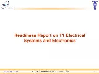
Report on T1 installation activities and achievements made during this shutdown. T1 detector in H8. T1 minus side. Minus side prepared for installation during Christmas Installed on 10 th January 2011 2 quarters moved from H8 to IP5 on 16 th Dec. 2010

E N D
Report on T1 installation activities and achievements made during this shutdown TIG meeting, 10 February 2011
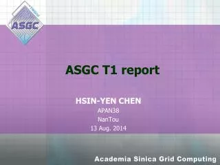
T1 detector in H8 TIG meeting, 10 February 2011
T1 minus side • Minus side prepared for installation during Christmas • Installed on 10th January 2011 • 2 quarters moved from H8 to IP5 on 16th Dec. 2010 • Moved to –HF platform on 2 risers, in the next days • Preliminary mechanical test • Temporary connections to the services • DAQ, LV, HV, DCS, DSS, Gas, Cooling • DAQ Readout and Slow Control test • Water leak detection cable installed. TIG meeting, 10 February 2011
T1 minus side • Insertion of the two quarters, one by one • CSC and BP clearances verification and adjustment • Frames and CMS envelope clearances verification and adj. • Truss position checked and aligned after survey. • Both quarters inserted into CMS endcaps • No interference of T1 on the alignement lasers • Gas and cooling connections • Cabling and grounding with final cables. • DAQ Readout and Slow Control test • Cabling off • - HF platform moved to 4 risers • Final cabling and readout test TIG meeting, 10 February 2011
Clearances between T1 CSC and BP on CMS minus side (mm) 5th layer 4th layer 3rd layer near far 27 27 24 26 26 26 31 30 28 26 26 25 25 22 28 32 27 25 2nd layer 1st layer 25 26 28 28 26 27 26 27 23 22 27 mm - actual size 26
T1 minus side TIG meeting, 10 February 2011
T1 minus side TIG meeting, 10 February 2011
T1 minus side TIG meeting, 10 February 2011
T1 plus side • Installed on 17th January 2011 • Same procedures than the Minus side. TIG meeting, 10 February 2011
Clearances between T1 CSC and BP on CMS plus side ( in mm) NEAR 5th layer 4th layer 3rd layer near far 23 26 22 25 21 23/24 35 35 27 27 27 26 35 32 32 28 29 26 2nd layer 1st layer 20 24 20 23 mm • First closing test • Without shimming 27 27 27 26 29 26 29 27 mm • Second closing • After shimming Picture from the minus side Measurement done by Roman.
Clearances between T1 CSC and BP on CMS plus side ( in mm) FAR 5th layer 4th layer 3rd layer near far 26 26 28 26 26 26 28 24 27 33 30 29 29 28 29 28 26 28 26 33 29 26 26 32 29 30 27 2nd layer 1st layer 26 26 28 • closing value • Closing test without mm 26 24 26 - theoretical value Dmitry mm 29 26 28 28 26 28 mm - actual size for the 5th layer the others layers theoretical value of Roman 26 29 27 26 30 28 Picture from the minus side Measurement done by Roman.
T1 plus side TIG meeting, 10 February 2011
T1 plus side TIG meeting, 10 February 2011
DSS LV OPFCs test • Each T1 quarter is powered independently. • 4 electro-mechanic breakers installed • Tested and deployed within DSS. • Electrical drawing updated • OPFCs AC input and DC output tested • 385V DC connections tested on both sides (rack and platform). TIG meeting, 10 February 2011
T1 services rack on HF platform • 4 minirack installed on HF platform • Safety smoke detector and Thermostat installed and tested (DSS) • All cables from the Counting Room traced and tested • Cooling circuit testedon –side, +side. TIG meeting, 10 February 2011
¼ T1 DCS and DSS systems • DCS system • 3 PT100 temperature sensors installed and checked • 2 on electronic boards and 1 on cooling plate • 2 active Radiation Monitor sensors installed and checked • 1 on 1st plane internal and 1 on 5th plane external • On the adjacent quarter the RadMon sensors are located on the same plane but opposite sides. • DSS system • 2 PT100 temperature sensors installed and checked • 2 on electronic boards. • 2 passive Radiation Monitor sensors installed TIG meeting, 10 February 2011
¼ T1 + Near (Yellow) _ Passive and Active RADMONs position RM 82 (IP-Side) = CSC 6th frame ROCs 45 = ROC C ROCs 23 5 T C 4 ROCs 01 = DOHM C 3 T 5 C C M = CFEC 4 C T 2 C C DOHM 3 1 M 5 C 2 M 4 C 1 C 3 B C 2 C PRM004 (~IP-Side) 1 B = IP5 C B C RM 84 (~IP-Side) PRM006 (IP-Side) TIG meeting, 10 February 2011
Slow Control Ring system 6th frame ROCs 45 = CSC ROCs 23 5 0x7E 4 ROCs 01 = ROC 3 0x77 5 0x7D 4 • 0x78 = DOHM 2 DOHM 3 1 0x76 5 = SCR cable 2 0x79 4 1 3 0x7C 2 1 0x7B = IP5 0x7A • SCR distributes Fast Command (L1, BC0, Calib, Reset) and LHC clock • Manage the F.E. settings through 16 I2C channels. • DOHM independent LV channel • Redundancy connection checked • All the ¼ T1 quarters passed the SCR tests. TIG meeting, 10 February 2011
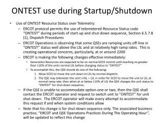
Joint test CMS and TOTEM (T1 and T2) • tested only T1 (10 Jan 2011) with CMS CSC ON, without problem • tested T1 and T2 (3-4 Feb 2011) with almost all CMS apparatus ON, without problem. • PIX, TK, ES (Preshower): out • RPC masked some towers in the trigger (to keep the rate within reason) • ECAL masked one trigger tower (ditto) • CASTOR HV OFF (due to miscommunication and sorted out later) and ON later TIG meeting, 10 February 2011
Effect of B on T1 position • Position checks during ramp to 3.8T • Small (order 1mm total) movements recorded on sensors“axial”(YE2 vs YE3) and “radial”(detectors vs vacuum chamber). • Very good correlation and +/- symmetry of displacements indicates that variation is due to the deformation of the end caps with B. TIG meeting, 10 February 2011
Conclusions We are ready. Thank you for your attention. TIG meeting, 10 February 2011