Download
1 / 14
140 likes | 150 Views
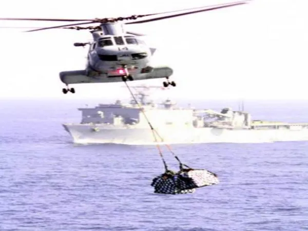
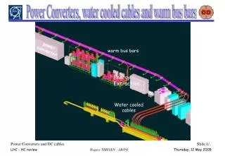
Insulated Bus Pipe (IBP), Revolutionary Alternative to Cables for Shipboard Power Distribution. March 12, 2019. NSRP 2019 All Panel Meeting. Background. Cables used since the advent of electrical distribution in 1800’s Primary cable advancements are in standardization and insulation materials

E N D
Insulated Bus Pipe (IBP), Revolutionary Alternative to Cables for Shipboard Power Distribution March 12, 2019 NSRP 2019 All Panel Meeting
Background • Cables used since the advent of electrical distribution in 1800’s • Primary cable advancements are in standardization and insulation materials • Skin effect and size precludes the use of large conductors for AC • Only option for supplying high current loads is parallel cables • Cable bend radius is over twelve times the overall diameter, or 26.4” minimum for typical 400 MCM cable • Cables run after a ship is fully assembled, does not support modular construction • Cable repulls costly and time-consuming
About IBP • Touch-safe power distribution able to be shaped into complex shapes • Multiple sizes available • AC applications up to 36 kV and 6.5 kA • DC applications up to 60 kV and 7 kA • Shielding/protection options • EM shielding • High temperature capability • Stainless steel outer layer • Prefabricated sections installed similarly to pipes • Bend radius limited by mechanical strength of conductor • 7.2kV AC/12kV DC at 2kA allows an 8” bend radius • Designed for 40+ year life
IBP Construction • Copper or aluminum conductor, can be solid or hollow • UP to 30’ sections are standard • Alternating layers of insulating/semiconducting crepe paper vacuum impregnated with resin • Up to IP68 construction • High temperature coatings • Shielding options • Multiple connecting methods to suit application • Connecting sleeve constructed similar to IBP
IBP Benefits/Advantages • Provides SWAP-C savings for increased endurance and design margin • Supports modular ship construction, savings cost, and schedule • Significant space and weight savings • Manufactured into complex shapes, can be placed in tight spaces • Rigid construction ensures accurate model • High abrasion resistance, increased survivability • Repairs easily accommodated, only the damaged section is replaced
IBP Product tested circa 2005 • IBP product tested at NAVSSES Philadelphia circa 2005 in support of early Ford class development • IBP not governed by any MIL-STD • Product tests based on electric cable tests as agreed between NAVSSES Philadelphia and interested program officers
Advancements • US manufactured IBP demonstrated to the Navy in a lab environment 1/24 through 2/1 • Incorporated in the power circuit during MVDC grounding testing at FSU CAPS facility
IBP Observations from demo • No issues observed during the two (2) week demonstration • AC IBP sections were exposed to 4.16 kV AC RMS line-to-line, 250 amps peak • DC IBP sections were exposed to as much as 5 kV DC, 200 amps • DC IBP is not expected to increase parasitic capacitance: • ~5.4 ηF IBP to ground (100 KHz to 20 MHz) • ~70 ηF overall DC side (including IBP) to ground • Real-time temperature sensing of IBP coupling bolts: • Identify coupling bolts that come loose over time
Project Status • Land Based Case Study of Insulated Bus Pipe for Ship Design • Culminated in lab test demo at FSU CAPS 1/24-2/1 2019 • Final Report to issue 3/20 • Qualification Testing of Insulated Bus Pipe (IBP) for Shipboard Introduction • Conduct electrical characterization, installation compliance, and shock and vibration tests • Build a low magnetic signature co-axial IBP for medium voltage direct current (MVDC) shipboard application • Generate IBP interface methods for power and loads • Generate a roadmap leading to IBP shipboard installation • Qualify a section of IBP for US Navy shipboard use
Conclusion • Provides numerous benefits to designers, builders, and the Navy • Benefits increased with high power loads • Increased budget margin for future upgrades • IBP has already passed a number of tests, and will work with Tech Warrant Holder community to determine qualification path • Once qualified, IBP will be available for shipboard integration
Status of qualification • Team Members: Tefelen, AeroNav Laboratories (Lead Test Lab), General Dynamics Bath Iron Works • Supportive Shipyards: Newport News Shipbuilding & Ingalls Shipbuilding • Certification Authorities: American Bureau of Shipping & Naval Surface Warfare Center Philadelphia Division • SEA 05Z approval of final qualification tests is required