Download
1 / 39
410 likes | 685 Views
CPU Internals. SOEN228, Fall 2003. Four Steps of Synchronization Handshake between Writer and Reader. Step 2: Writer Signals with Token. Step 1: Writer Writes Data. Writer. IOSCR. data. data. IODR. Step 3: Reader Reads Data. Step 4: Reader Deletes Token. Reader. Reader. data.

E N D
CPU Internals SOEN228, Fall 2003 Serguei Mokhov, mokhov@cs.concordia.ca
Four Steps of Synchronization Handshake between Writer and Reader Step 2: Writer Signals with Token Step 1: Writer Writes Data Writer IOSCR data data IODR Step 3: Reader Reads Data Step 4: Reader Deletes Token Reader Reader data old data Serguei Mokhov, mokhov@cs.concordia.ca
Case: Programmed Input from Keyboard Step 2 Step 1 Keyboard Controller ASCII Key data data IODR Step 3 Step 4 CPU CPU data old data copy:char IODR -> reg0 copy #0 -> IOSCR Serguei Mokhov, mokhov@cs.concordia.ca
Case: Programmed Input from Keyboard (2) • The ready flag (full/empty bit) is typically a particular bit in the status register of the I/O port. • The flag is equal to 1 iff the data register (IODR) is holding valid data yet to be read (consumed) by the reader. It will be reset to 0 when the reader has read the data register. • In this way, the I/O port can be used to carry out a transaction by using busy-wait loop: each party will loop indefinitely to test the status flag before it produces/consumes. • Drawback: Programmed I/O via busy-wait loops consume processing power (time); for example, when the CPU executes in the busy-wait loop, no useful work is done by the processor. • Compare CPU speed and human input speed! Serguei Mokhov, mokhov@cs.concordia.ca
Interrupts and Interrupt Handler Serguei Mokhov, mokhov@cs.concordia.ca
Interrupts and Interrupt Handler • Programmed I/O suffers from the fact that the participants in an I/O transfer may have greatly diversified speeds. • Using the keyboard example, we know that the system could read thousands of times faster than the typing speed of the fastest typist. • Hence, the fast partner has to wait for the slow partner, leading to a huge waste of resources (for example, computational resources). • The asynchrony between the synchronous computer and the external world often requires better solutions. • Interrupts is one such a solution. Serguei Mokhov, mokhov@cs.concordia.ca
Basic Principle (1) • The computer will assume that I/O activities are temporally suspended (such as when the human has not yet struck the next key) and schedule itself to handle other computational task (program). Serguei Mokhov, mokhov@cs.concordia.ca
Basic Principle (2) • When I/O attention is needed, the external action is translated into an interrupt signal that gets into the CPU. • This serves as a trap, forcing the CPU to suspend its current (possibly computational) program and transfer its flow of control to an interrupt handling subroutine. • This is equivalent to a hardwired subroutine jump. Serguei Mokhov, mokhov@cs.concordia.ca
Basic Principle (3) • The interrupt service routine (handler) may be chosen from a few candidates, based on the type of interrupt received. • When finished, control could be returned to the program that was interrupted, just like subroutine return. Serguei Mokhov, mokhov@cs.concordia.ca
Case: Interrupt Input from Keyboard Step 2 Step 1 Keyboard Controller Interrupt CPU ASCII Key data data IODR CPU Acknowledges the Interrupt Step 3: CPU executes ISR Step 4: Completion of ISR CPU CPU data old data copy:char IODR -> 0 copy #0 -> IOSCR Serguei Mokhov, mokhov@cs.concordia.ca
Interrupt Processing • Interrupt I/O involves the use of hardware signals: • when an I/O port needs CPU attention, an interrupt signal is sent and later received by the CPU. • The CPU can acknowledge the interrupt by returning an INTA (interrupt acknowledge signal) and subsequently jumps to the interrupt service routine (ISR) to process/serve the I/O port. • The key feature is the asynchrony: the CPU is free to do something else until attention is needed. Hence the busy-wait is avoided. Serguei Mokhov, mokhov@cs.concordia.ca
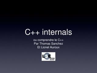
Enable keyboard input and interrupts Enable keyboard input and interrupts Return from Go to do other useful thingies Read/process keyboard data buffer Interrupt Done? Yes Other CPU-bound process No Interrupt Service Routine Serguei Mokhov, mokhov@cs.concordia.ca
Key Observations • Since the CPU is freed from busy-wait, it could be switched to perform other useful program executions. • Thus, it improves the utilization of the system, leading to a much better response time for all users. • I/O can proceed asynchronously. There is no assumption on the exact timing of events. Serguei Mokhov, mokhov@cs.concordia.ca
Instruction Cycle and Interrupts IF ID OF EX OS • Instruction Cycle: • Interrupt Request (INTR) is tested at end of Cycle • If INTR is ‘true’, then a hardwired subroutine jump to the interrupt service routine (ISR) will be used as the next instruction to be executed. • Notice that the current program is interrupted and the return address is pushed on the stack as part of the subroutine call. Interrupt? call ISR Yes No Serguei Mokhov, mokhov@cs.concordia.ca
Interrupt Acknowledge Interrupt Acknowledge Interrupt • 1: Interrupt Service Routine: • CPU reads data from device port. • 2: Interrupt Service Routine: • CPU transfer the data read to memory. CPU Memory Unit Device 2 1 Serguei Mokhov, mokhov@cs.concordia.ca
Interrupt Acknowledge (2) • Interrupt Acknowledge (INTA) is the signal from the CPU indicating that the CPU is ready to handle the interrupt. • Typically, this signal is used to handshake with the device that has caused the interrupt so that the device can identify itself in the form of an interrupt vector. • The interrupt vector is received by the CPU and is used as a pointer or address to the needed interrupt service routine. • Problem: • How can the CPU scale up to the number of external interrupts? Serguei Mokhov, mokhov@cs.concordia.ca
Multiplicity of Interrupt Sources • Interrupts can come from multiple devices or sources. • In a typical computer system, interrupts could be caused by: • Power Failure • Timer • I/O Devices such as disks, terminals, printers etc. • Hardware error conditions (parity error, etc.) • Software error conditions (divide-by-zero, etc.) • It raises a couple of issues: • Priority • Interrupt Identification Serguei Mokhov, mokhov@cs.concordia.ca
Priority • Can we allow an interrupt to interrupt an interrupt handler? Why? Which interrupt should be served next? • Usually, priorities can be assigned to various sources of interrupt according to some criteria, such as the penalty of not reacting in time, or the expected return if served. • So, the following priority assignment is quite typical: • Power failure; Timer; Error; I/O. • Each sub-class of priority may correspond to a single bit of signal sent to the CPU interface. • This is the interrupt signal of that sub-class. • In implementation, the instruction cycle of the CPU is changed such that at the end of a cycle, the existence of an unmasked (enabled) interrupt forces the CPU to execute the equivalence ofjump:subroutine interrupt_handler. Serguei Mokhov, mokhov@cs.concordia.ca
Interrupt Identification • The choice of interrupt_handler can be resolved in a number of ways. • In general, the CPU must identify the source of the interrupt (with the highest priority). • This identification can be achieved using • Software polling: the interrupt handler can be programmed to poll through the various I/O interfaces (status registers), highest priority interface first. • Once it comes across an interface that indicates its interrupt status, then the handler proceeds to execute the corresponding handler for that interface. Serguei Mokhov, mokhov@cs.concordia.ca
Software Polling Flowchart Interface 1 ready? ISR for 1 Yes No Interface 2 ready? ISR for 2 Yes No Interface N ready? ISR for N Yes No Return to the Interrupted Program Serguei Mokhov, mokhov@cs.concordia.ca
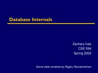
Hardware Polling (Daisy Chain) • The polling can be done by hardware in which the interrupt requests from all interfaces (devices) are “OR’ed” together to interrupt the CPU. • When the CPU acknowledges to the interrupt via INTA (interrupt acknowledge), the latter signal is allowed to propagate through the interfaces arranged in a daisy chain, with the highest priority interface receiving the INTA first. • An interface propagates INTA to its next lower priority neighbor only if it has not generated an interrupt request; otherwise, it will stop the propagation and identify itself to the CPU (for example, by depositing its ID onto the system bus). • Notice that INTR and INTA represent an instance of the 4-phase handshaking solution explained earlier. Serguei Mokhov, mokhov@cs.concordia.ca
Daisy Chain Priority Scheme To Data Bus • INTR: Interrupt Request (to CPU) • INTA: Interrupt Acknowledge (from CPU) • INTA is propagated from device 1 to device N, and it stops at the first device that has generated an interrupt. Interrupt Vector INTA Device Interface 1 Device Interface 2 Device Interface N Control Bus INTR1 INTR1 INTRN INTR Serguei Mokhov, mokhov@cs.concordia.ca
Interrupt Vector • A typical way is to associate an interrupt vector with entriesfor each interrupt source. • Entries in this interrupt vector actually point to (directly or indirectly) the starting address of the required interrupt service routine. • For example, the interrupt handler for the keyboard is immediately executed once the interrupt source is known to the CPU. Serguei Mokhov, mokhov@cs.concordia.ca
Enabling/Disabling of Interrupts • Even though the use of priority in some sense already disables lower priority interrupts from interrupting a higher priority interrupt service routine, it is often necessary to disable certain interrupts dynamically. • An example would involve an input process and an output process from before. • The input process reads a character from the keyboard and the output process writes the character to the display. • The input and output must be done in a sequence alternately. • To synchronize the two processes, we could use the enabling/disabling feature in interrupts. Serguei Mokhov, mokhov@cs.concordia.ca
Enabling/Disabling of Interrupts (2) • The Enabling/Disabling can be accomplished using MASKING. • A mask flag is associated with every interrupt source. • An interrupt will be received by the CPU only if it has not been masked off, i.e., the associated mask has not been reset. • The follow up diagram illustrates such a masked interface. Serguei Mokhov, mokhov@cs.concordia.ca
Priority Encoder Resolution of Interrupts Eg: Intel 82C59A Priority Encoder INTR1 INTR2 : : : INTRN INTA 1 2 3 ... N Interrupt Mask Register INTR : Serguei Mokhov, mokhov@cs.concordia.ca
Context Switching (2) • Since the handler will use the registers and even destroy their content, it will be important to preserve these register contexts so that when the interrupted program is returned, the original context is still available and intact. • So, an assume-nothing interrupt handler will adopt the following structure: interrupt_handler: push reg0 push reg1 :::: take care of service pop reg7 pop reg6 :::: return Serguei Mokhov, mokhov@cs.concordia.ca
Drawbacks? • Is there any drawback using interrupt processing? • Interrupt is asynchronous and frees the CPU to perform other tasks via proper context switching. • However, there is a price being paid every time context switching takes place. • Alternative: • Why not free the CPU entirely from doing the work of the interrupt handler, except once-in-a-while? Serguei Mokhov, mokhov@cs.concordia.ca
Direct Memory Access(DMA) Serguei Mokhov, mokhov@cs.concordia.ca
Motivation • I/O transfer often involves transferring a large “chunk” of data to or from the computer, for example, disk transfer involves multiple sectors. • Much of the interrupt handler for such a disk transfer involves moving memory pointers and transferring the data until the needed number of bytes are transferred. • The software managed transfer can be replaced by a hardware component called DMA controller. Serguei Mokhov, mokhov@cs.concordia.ca
DMA Controller • A DMA controller is a hardware interface containing: • data register: • data to be transmitted • status and control register: • status and control • word/byte count register: • remaining word count • memory address register: • next memory location • device address register: • next device address Serguei Mokhov, mokhov@cs.concordia.ca
A Typical DMA Controller Data Count Data Lines Data Register Address Register Address Lines Control Logic DMAR DMAA INTR Read Write Serguei Mokhov, mokhov@cs.concordia.ca
DMA Controller (2) • A DMA controller (DMAC) can be considered as an intelligent I/O port. • We will illustrate its operation via a disk transfer example. • Reading 1K byte from Disk Address (1234) to RAM address (1000). • The CPU executes only the following: copy #1234h -> device_address_register; copy #1000h -> memory_address_register; copy #1024 -> word_count_register; copy #1 -> device_status_register; ::::: ::::: ::::: Serguei Mokhov, mokhov@cs.concordia.ca
DMA Controller (3) • The CPU is involved only as a master; it initializes the disk address to be 1234h, followed by the target storage address in RAM to be 1000h and the word count of 1024 in the word count register. • Then it writes #1 into the device_status_register. This tells the disk controller (the DMAC) to start reading. • Afterwards, the CPU moves on to do whatever else is there to do. • As usual, the CPU can be interrupted later if attention is needed. Serguei Mokhov, mokhov@cs.concordia.ca
Behavior of the DMAC • The DMAC proceeds to control the disk drive to access the desired sector (address 1234h). • Afterwards, it proceeds to conduct the transfer of 1024 bytes from disk to RAM starting from RAM location 1000h. • The transfer is conducted by stealing memory cycles from the CPU (the memory is connected to both the CPU and the DMAC via System Bus). Serguei Mokhov, mokhov@cs.concordia.ca
Comparing DMA with Interrupt I/O • You pay a price in using DMA. It incurs additional hardware and hence cost. • What have you gained? • Suppose the total transfer time of 1K bytes from the disk takes 1 ms. • During this interval, the CPU is not paying any attention to the DMAC. • If interrupts are used, the CPU will be interrupted 1024 times. • Suppose the interrupt handler for the disk takes 0.0005 ms to execute. • The CPU will have to spend 0.512 ms to serve the interrupts. • Equivalently, its availability is reduced by 50%. Serguei Mokhov, mokhov@cs.concordia.ca
Comparing DMA with Interrupt I/O • Notice also that if the external device is fast, interrupt processing to update the external device may be too slow: • interrupt handler involves a software solution that is usually slower than its hardware counterpart. • As an immediate example, you can redo the comparison assuming that the disk completes the transfer in 0.5 ms instead of 1 ms. What will happen? DMA DMA CPU Memory Unit Device Serguei Mokhov, mokhov@cs.concordia.ca
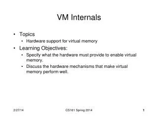
System BusStructure CPU Memory 7 6 5 4 3 2 1 7 2 1 Address Bus Data Bus Control Bus 7 1 2 6 5 4 3 3 4 1 2 7 2 7 1 DMA I/O Interrupt I/O Programmed I/O 4 1: Data 2: Address Interrupt I/O 3: INTR 4: INTA Daisy Chain 5: DMAR 6: DMAA ::: 7: Read / Write Serguei Mokhov, mokhov@cs.concordia.ca
Library for PA4 • /pkg/nasm/lib/libcomp228.a Serguei Mokhov, mokhov@cs.concordia.ca