Download
1 / 26
270 likes | 478 Views
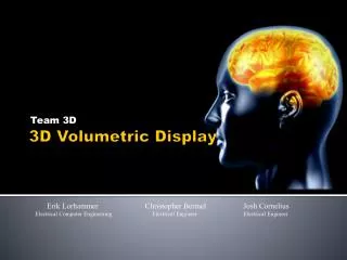
Team 3D. 3D Volumetric Display. Erik Lorhammer Christopher Bermel Josh Cornelius Electrical Computer Engineering Electrical Engineer Electrical Engineer. Overview. Objectives 3D Volumetric Display

E N D
Team 3D 3D Volumetric Display Erik Lorhammer Christopher Bermel Josh Cornelius Electrical Computer Engineering Electrical Engineer Electrical Engineer
Overview Objectives • 3D Volumetric Display • System loads pictures from an SD card to DDR SDRAM and sends pictures to a projector in a specified order over a VGA interface • Project images onto a screen rotating at 600rpm, the rotation of this screen produces a 3D image • Desired image is 3D CU logo in two colors
Processor • Altera Cyclone II FPGA • Development: • DE2 Board with EP2C35F672C6N Cyclone II • 33216 LE’s • Implementation: • Sparkfun Breakout Board with EP2C8Q208C8N Cyclone II • Less Memory Available On-Chip • SDRAM will contain all storage and program information so not a big concern. • One-Fifth Logic Elements (8256 LE’s) • Make sure that design fits within this constraint while working on DE2 board. • Program via Jtag interface • Elements being programmed in Verilog • Running at 100 MHz, initial Fmax results from Quartus II show critical path Fmax to be ~167MHz so have some headroom if frame rate is not adequate.
Memory • SDRAM • Micron - MT46V32M8P-6T:G TR • 256MB DDR SDRAM • SRAM • Acts as Frame Buffer • At least 1MB to store two images • One image is ~300KB, want to have two buffers in order to simultaneously put a new image into buffer while reading the older one • Recent Decision so part has not been selected yet • SD-Card • Kingston 1GB Card • Will allow for up to four different image sets to be on SD-Card for easy changing of 3D image without going back to laptop • Pre-defined software package takes care of bus interactions and all required communications.
VGA & Optical Encoder • VGA • 640 x 480 at 8-bits Color • Images are stored in frame buffer in SRAM • Full image sets are stored in SDRAM • Mega Function provided by Altera University Program. • 640 x 480 at 10-bits Color (still researching 10-bits • May not be adequate for our needs backup is designing our own VGA Controller • Optical Encoder • CUI Inc. High Resolution Encoder • Keeps control board up to date on mirror location • Will allow synchronization of frame output every 360 degrees (~24 frames)
Debug / Testing • Code in C / C++ using Nios II IDE (eclipse) • Included debug tools • Access to registers • Stepping through program • Program LED as additional debugging tools • LEDs light at certain points in code, after certain actions have been completed • Quartus II Software • Tools to get accurate timing between elements • Test Functionality at each step • Each Component can be individually tested • SDRAM proper timing • Moving images from SD-Card to SDRAM • Outputting a single picture on VGA • Proper implementation of Frame Buffer on SRAM
Mechanical Design Specifications • Steel Turntable • 12.06” outer diameter • 6.33” inner diameter • HDPE Ring and Polycarbonate Arches • Bolted to steel turntable • Holds projection screen in place • Mirrors are mounted to the ring • Friction Drive • Motor spins small wheel that drives large ring
Optical Design Specifications • Projector • Standard DLP projector borrowed from department • Custom focusing lens • Allows for large projection image to be focused on a small screen at a short distance • Designed with help from Professor McLeod • Mirrors • Three mirrors for image transmission • Translucent Screen • 1/8” Acrylic sheet
Milestone One • Control Board fully realized • All components placed in Quartus II and verification testing beginning • Testing: • SD-Card properly initialized by board • SD-Card transferring images to SDRAM • SDRAM transferring images to SRAM Frame Buffer • VGA Controller taking images from SRAM Frame Buffer and outputting to projector • Projector image clear and crisp • First PCB revision • Mechanical system built and under test • Screen rotating at 600 RPM • Mirror defined • Lens ordered
Milestone Two • Control Board finished and tested • Fully implemented on PCB Schematics • Second PCB revision ordered and delivered • Secondary objectives in Design and Test • LCD panel status screen • Other “Cool Ideas” not yet thought of • Second PCB revision ordered • Full knowledge if third revision needed • Mechanical system only needs a few tweaks • Simple 3D image is displayed (Red Ball)
Division of Labor • Chris • Printed Circuit Board • Mechanical System • Erik • VGA Interface • NIOS II System • Memory Interfaces • Josh • SD Interface • Optics • Image Processing