Download
1 / 12
120 likes | 132 Views
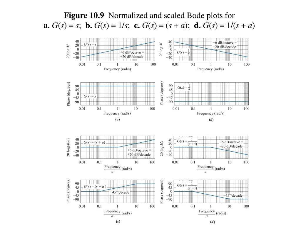
Figure 10.9 Normalized and scaled Bode plots for a. G ( s ) = s ; b. G ( s ) = 1/ s ; c. G ( s ) = ( s + a ); d. G ( s ) = 1/( s + a ). Figure 10.11 Bode log-magnitude plot for Example 10.2: a. components; b. composite.

E N D
Figure 10.9 Normalized and scaled Bode plots fora. G(s) = s; b. G(s) = 1/s; c. G(s) = (s + a); d. G(s) = 1/(s + a)
Figure 10.11Bode log-magnitude plot for Example 10.2:a. components; b. composite
Figure 10.37 穩定度指標Gain and phase margins on the Bode diagrams
Ch. 11-2 Use frequency response techniques to adjust the gain to meet a transient response specification. Ch. 11-3 Use frequency response techniques to design cascade compensators to improve the steady-state error Ch. 11-4 Use frequency response techniques to design cascade compensators to improve the transient response. Ch. 11-5 Use frequency response techniques to design cascade compensators to improve both the transient response and the steady-state error.
Figure 11.1Bode plots showing gain adjustment for a desired phase margin
Ch. 11-2 Use frequency response techniques to adjust the gain to meet a transient response specification. Ch. 11-3 Use frequency response techniques to design cascade compensators to improve thesteady-state error Ch. 11-4 Use frequency response techniques to design cascade compensators to improve the transient response. Ch. 11-5 Use frequency response techniques to design cascade compensators to improve both the transient response and the steady-state error.
Bode plots with ess improved ΦM = 59.2 o Lag 補償:變更與 0dB交點, 獲取ΦM = 69.2 o and given unity gain
Ch. 11-2 Use frequency response techniques to adjust the gain to meet a transient response specification. Ch. 11-3 Use frequency response techniques to design cascade compensators to improve thesteady-state error Ch. 11-4 Use frequency response techniques to design cascade compensators to improve the transient response. Ch. 11-5 Use frequency response techniques to design cascade compensators to improve both the transient response and the steady-state error.
design cascade compensators to improve the transient response (Lead compensation)