Download
1 / 27
340 likes | 834 Views
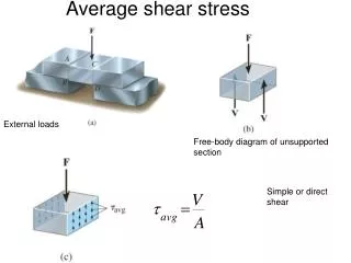
Shear Stress and Strain. Shear Stress, Shear Strain, Shear Stress and Strain Diagram. Shear Stress. V: shear load ( the force is acted on the center of designated area) A: area of the plane. Shear Stress: Load (V). Shear Stress: pin and rivet. V A = 0.5 F A. Shear Stress: pin and rivet.

E N D
Shear Stress and Strain Shear Stress, Shear Strain, Shear Stress and Strain Diagram
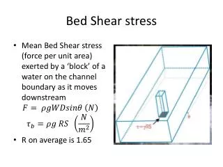
Shear Stress V: shear load ( the force is acted on the center of designated area) A: area of the plane Lecture 1
Shear Stress: pin and rivet VA= 0.5 FA
Shear Stress: pin and rivet What is the value of V and A?
Shear Stress: pin and rivet What is the value of V and A? Sketch its FBD to show the value of V Vx= Vy = Total VR = 1 bolt: V= 2 parallel rivet V = 3 parallel rivet V = V=
Shear Stress: torque Shear load due to torsion T V V Equilibrium equation:
Shear Stress: torque Calculate the V and A. Sketch the FBD. T= 10 Nm ccw Bolt d = 10mm Position of the bolt R = 100 mm
Allowable Shear Stress • Considered as SAFE • Considered as FAIL • Safety Factor • Safe F.S >= 1 • Fail F.S < 1 The allowable stress is the maximum shear stress allowed due to the properties of the material.
Shear Strain 3 Normal strains (ex, ey, ez ) and 3 shear strains (gxy, gyz, gxz) are detected. Shear strain is detected the changes in angle is detected.
Approximate angles between three sides Approximate length of the edges
The Shear Stress–Strain Diagram • For pure shear, equilibrium requires equal shear stresses on each face of the element. • When material is homogeneous and isotropic, shear stress will distort the element uniformly.
The Shear Stress–Strain Diagram • For most engineering materials the elastic behaviour is linear, so Hooke’s Law for shear applies. • 3 material constants, E, and G are actually related by the equation G = shear modulus of elasticity or the modulus of rigidity
Example A specimen of titanium alloy is tested in torsion and the shear stress–strain diagram is shown. Find the shear modulus G, the proportional limit, and the ultimate shear stress. Also, find the maximum distance d that the top of a block of this material could be displaced horizontally if the material behaves elastically when acted upon by a shear force V. What is the magnitude of V necessary to cause this displacement?
Example Discuss the approach? G: slope of the elastic curve Yield shear stress: from curve Ultimate shear stress: from curve tan (0.008 rad) = d/50
Solution: The coordinates of point A are (0.008 rad, 360 MPa). Thus, shear modulus is By inspection, the graph ceases to be linear at point A. Thus, the proportional limit is This value represents the maximum shear stress, point B. Thus the ultimate stress is
Since the angle is small, the top of the will be displaced horizontally by The shear force V needed to cause the displacement is
Solve it! The shear stress-strain diagram for a steel is shown in the figure. If a bolt is having a diameter of 20 mm is made of this material and used the double lap joint, determine the modulus of elasticity E and the force P required to cause the material to yield. Take u = 0.3. Discuss the approach???
FBD of the bolt 2) Ssy = 420 MPa, calculate the P 3) G is slope of the curve 4) Calculate E based on value G and u
Review Question A load W = 1000 kg is supported by a 3‐cable system as shown in figure 1. The cable run along 2 pulleys F and D which is attached to the solid wall by a round beam EF and CD both of which are 30mm diameter and 300mm long. Ignore the mass of cable and beam. All cables are the same size. The sizes of the pulleys at D & F can be ignored. Gravity = 9.81m/s2 Answer the following questions: Calculate the tension of cable AB, BD, and BF Calculate the diameter of the cable is the allowable stress is 140 MPa, assume all the cables have the same diameter. Find the internal stress at the mid point of round beam FE
TBF TBD Equilibrium W Stresses: the highest will be cable BA as it has the highest load
Internal forces at middle of BE (150mm) TBF P V M TBF Lecture 1
Example The joint is fastened together using two blots. Determine the required Diameter of the bolts if the failure shear stress of the bolt is 350 Mpa. Use factor of safety of F.S = 2.5.
V for each bolt Shear stress resulted from V Allowable shear stress Therefore:
Example The A-36 steel wire AB has a cross-sectional area of 10 mm2 and unstretched when q =45o. Determine the applied load P needed to cause q = 44.9o.
Initial length LAB Final elongation Strain Normal Stress on cable
The tension of the cable FBD when the cable is stretched O P