Download
1 / 44
590 likes | 1.44k Views
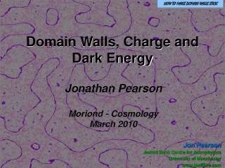
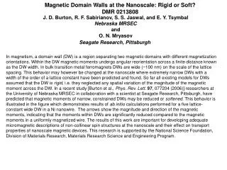
Magnetic Domain and Domain Walls. 1. Domain walls Bloch wall Neel wall Cross-Tie wall 2. Magnetic domains Uniaxial wall spacing Closure domain Stripe domains 3. Some methods for the domain observation SEMPA MFM Magneto-optical. Relevant Energy Densities. Exchange energy.

E N D
Magnetic Domain and Domain Walls 1. Domain walls • Bloch wall • Neel wall • Cross-Tie wall 2. Magnetic domains • Uniaxial wall spacing • Closure domain • Stripe domains 3. Some methods for the domain observation • SEMPA • MFM • Magneto-optical
Relevant Energy Densities Exchange energy Magnetostatic Magnetocrystalline Magnetoelastic Zeeman
In 1907, Weiss Proposed that magnetic domains that are regions inside the material that are magnetized in different direction so that the net magnetization is nearly zero. Domain walls separate one domain from another. P. Weiss, J.Phys., 6(1907)401.
Schematic of ferromagnetic material containing a 180o domain wall (center). Left, hypothetical wall structure if spins reverse direction over one atomic distance. Right for over N atomic distance, a. In real materials, N: 40 to 104.
magnified sketch of the spin orientation within • a 180o Bloch wall in a uniaxial materials; (b) an appro- • ximation of the variation of θ with distance z through • the wall.
Bloch Wall Thickness ? In the case of Bloch wall, there is significant cost in exchange energy from site i to j across the domain wall. For one pair of spins, the exchange energy is : , Surface energy density is , In the other hand, more spins are oriented in directions of higher anisotropy energy. The anisotropy energy per unit area increases with N approximately as
The equilibrium wall thickness will be that which minimizes the sum with respect to N thus the wall thickness The minimized value No is of order , where A is the exchange stiffness constant. A=Js2/a ~10-11 J/m (10-6 erg/cm), thus the wall thickness will be of order 0.2 micron-meter with small aniso- tropy such as many soft magnetic materials
Wall energy density ? The wall energy density is obtained by substituting into To give
Neel Wall Comparision of Bloch wall, left, with charged surface on the external surface of the sample and Neel wall, right, with charged surface internal to the sample.
Energy per unit area and thickness of a Bloch wall and a Neel wall as function of the film thickness. Parameters used are A=10-11 J/m, Bs=1 T, and K=100 J/m3.
In the case of Neel wall, the free energy density can be approximated as Minimization of this energy density with respect to δN gives For t/δN ≤1, the limiting forms of the energy density σN and wall thickness δN follow from above Eq.
Neel wall near surface Calculated spin distribution in a thin sample containing a 180o domain wall. The wall is a Bloch wall in the interior, but it is a Neel wall near the surface.
Cross-tie wall The charge on a Neel wall can destabilize it and cause it to degenerate into a more complex cross-tie wall
Magnetic Domains Once domains form, the orientation of magnetization in each domain and the domain size are determined by Magnetostatic energy Crystal anisotropy Magnetoelastic energy Domain wall energy
Domain formation in a saturated magnetic material is driven by the magnetostatic (MS) energy of the single domain state (a). Introduction of 180o domain walls reduces the MS energy but raises the wall energy; 90o closure domains eliminate MS energy but increase anisotropy energy in uniaxial material
Uniaxial Wall Spacing The number of domains is W/d and the number of walls is (W/d)-1. The area of single wall is tL The total wall energy is . The wall energy per unit volume is
Domain Size d ? The equilibrium wall spacing may be written as Variation of MS energy density and domain wall energy density with wall spacing d.
For a macroscopic magnetic ribbon; L=0.01 m, σw= 1mJ/m2, uoMs= 1 T and t = 10um, the wall spacing is a little over 0.1 mm. The total energy density reduces to According to the Eq.(for do) for thinner sample the equilibriumwall spacing do increases and there are fewer domains.
A critical thickness for single domain (The magnetostatic energy of single domain) Single domain size Variation of the critical thickness with the ratio L/W for two Ms (σdw=0.1mJ/m2)
Size of MR read heads for single domain ? If using the parameters: L/W=5, σdw≈ 0.1 mJ/m2,uoMs= 0.625 T; tc ≈13.7 nm; Domain walls would not be expected in such a film. It is for a typical thin film magnetoresistivity (MR) read head.
Closure Domains Consider σ90 =σdw /2, the wall energy fdw increases by the factor 1+0.41d/L; namely δfdw≈ 0.41σdw/L Hence the energies change to Geometry for estimation of equilibrium closure domain size in thin slab of ferro- magnetic material. If Δftot < 0, closure domain appears.
Energy density of △ftot versus sample length L foruo Ms=0.625 T, σ=0.1 mJ/m2, Kud=1mJ/m2, and td=10-14 m2.
Domains in fine particles for large Ku Single domain partcle σdw πr2 =4πr2(AK)1/2 △EMS≈ (1/3)uo Ms2V=(4/9)uo Ms2πr3 The critical radius of the sphere would be that which makes these two energies equal(the creation of a domain wall spanning a spherical particle and the magnetostatic energy, respectively). rc≈ 3nm for Fe rc≈ 30nm for γFe2O3
Domains in fine particles for small Ku If the anisotropy is not that strong, the magnetization will tend to follow the particle surface The spin rotate by 2π radians over that radius (a) (b) (a) A domain wall similar to that in bulk; (b) The magneti- zation conforms to the surface.
The exchange energy density can be determined over the volume of a sphere by breaking the sphere into cylinders of radius r, each of which has spins with the same projection on the axis symmetry =2(R2-r2)1/2 Construction for calculating the exchange energy of a particle demagnetized by curling.
If this exchange energy density cost is equated to the magnetostatic energy density for a uniformly magnetizes sphere, (1/3)uoMs2, the critical radius for single-domain spherical particles results: Critical radius for single-domain behavior versus saturation magnetization. For spherical particles for large Ku, 106 J/m3 and small one.
Stripe Domain Spin configuration of stripe domains
Spin configuration in stripe domains The slant angle of the spins is given as, θ = θo sin ( 2πx/λ ) The total magnetic energy (unit wavelength); When w >0 the stripe domain appears.
Minimizingwrespect toλ (1) Using eq.(1) we can get the condition for w>0,
Striple domainsin 10Fe-90Ni alloys film observed by Bitter powder (b) After switch off a strong H along the direction normal to striple domain. (a) After switch of H along horizontal direction. (c)As the same as (b), but using a very strong field.
The stripe domain observed in 95Fe-5Ni alloys film with 120 nm thick by Lolentz electron microscopy.
Superparamagnetism ProbabilityP per unit time for switching out of the metastable state into the more stable demagnetzed state: the first term in the right side is an attempt frequancy factor equal approxi- mately 109 s-1. Δf is equal to ΔNµo Ms2 or Ku . For a spherical particle with Ku = 105 J/m3 the superparamagnetic radii for stability over 1 year and 1 second, respectively, are
Paramagnetism and Superparamagnetism Paramagnetism describes the behavior of materials that have a local magnetic moments but no strong magnetic interaction between those moments, or. it is less than kBT. Superparamagnetism:the small particle shows ferromagnetic behavior, but it does not in paramagnete. Application of an external H results in a much larger magnetic response than would be the case for paramagnet.
Superparamagnetism The M-H curves of superparamagnts can resemble those of ferromagnets but with two distinguishing features; (1)The approachto saturation follows a Langevin behavior. (2) There is no coecivity. Superpara- magnetic demagnetization occurs without coercivity because it is not the result of the action of an applied field but rather of thermal energy. paramagnetism Langevin function versus s; M = NµmL(s); s = µmB/kBT
Scanning Electron Microscopy with Spin Polarization Analysis (SEMPA) Principle: when an energetic primary electron or photon enters a ferromagnetic material, electron can be excited and escape from the material surface. The secondary electrons collected from the small area on the surface are analyzed to determine the direction of magnetization at the surface from which they were emitted. The vertical p component The horizantal p component (a) 3.5x3.5 µm2 (a) magnetic surface domain structure on Fe(100). The arrows indicate the measured polarization orientation in the domains. The frame shows the area over which the polari- zation sistribution of (b) is averaged.
Below, structure of Fe film/ Cr wedge/ Fe whisker illustrating the Cr thickness dependence of Fe-Fe exchange. Above, SEMPA image of domain pattern generated from top Fe film. (J. Unguris et al., PRL 67(1991)140.)
Magnetic Force Microscopy (MFM) Geometry for description of MFM technique. A tip scanned to the surface and it is magnetic or is coated with a thin film of a hard or soft magnetic material.
Domain structure of epitaxial Cu/tNi /Cu(100) films imaged by MFM over a 12 µm square: (a) 2nm Ni, (b) 8.5 nm Ni, (c) 10.0 Nm Ni; (d) 12.5nm Ni (Bochi et al., PRB 53(1996)R1792).
Magneto-optical Effect θ k is defined as the main polarization plans is tilted over a small angle; εk= arctan(b/a).
(a)Assembly of apparatus (b) Rotation of polarization of reflecting light.
Domain on MnBi Alloys The magnetic domains on the thin plate MnBi alloys observed by Magneto-optical effect; (a) thicker plate (b) medium (c) thinner. (Roberts et al., Phys. Rev., 96(1954)1494.)
Other Observation Methods (a) Bitter Powder method; (b) Lorentz Electron Microscopy; (c) Scanning Electron Microscopy; (d) X-ray topograhy; (e) Holomicrography