Download
1 / 47
500 likes | 820 Views
Design of Thermal Control Sub-System(TCS) Picosat course May 18, 2006 IAA,National Cheng Kung University, Tainan J. H. Chou Department of Engineering Science National Cheng Kung University. Outline I. Review of TCS key concepts II. Design considerations III. YamSat thermal design

E N D
Design of Thermal Control Sub-System(TCS) Picosat course May 18, 2006 IAA,National Cheng Kung University, Tainan J. H. Chou Department of Engineering Science National Cheng Kung University
Outline I. Review of TCS key concepts II. Design considerations III. YamSat thermal design IV. Summary
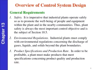
I. Review . Why do we need TCS for PicoSat? . Working Temperature: sensors, electronics and materials . Temperature uniformity: thermal stress . PicoSat environment: cold and near vacuum . Energy source and sink . Thermal balance and heat transfer path
Picosat thermal environments . Three phases: .launch .mission lifetime .reentry self-destruction
Key issues: . Environment . Components temperature specification . Heat source . Heat sink . Heat transfer path and mechanisms . Control techniques
Typical temperature range for selected satellite components Components Typical temperature range, ℃ Batteries 5 to 20 Electronics 0 to 40 Infrared detectors - 200 to – 80 On-board computer - 10 to 50 Propellant, hydrazine 7 to 35 Solar arrays - 100 to 100 Structures - 45 to 65 Note: reference only. Check manufacturer’s data for details.
Radiation Property Values Radiation Computer Program (Geometric Math Model) Radiation Exchange Factors and View Factors Spacecraft Orientation and Attitude Thermal Control Hardware Elements Spacecraft Geometry Radiation Absorbed on Exterior Surface Thermal Analyzer Computer Program (Thermal Math Model) Electrical Power Dissipation Component-Level Tests Thermophysical Property Values Predicted Thermal Performance Requirements -Temperature Limits -Survivability System-Level Tests Comparison II. TCS design considerations
Some heat sources: . Solar and planetary radiation . Planetary reflection . Equipment heat sources: electronic devices batteries propulsion . Reentry atmospheric frictional heating
P Emitted Radiation Mean value of Direct Solar Flux 1385+5 W/m2 Low-Earth Orbit Spacecraft Gs Albedo (30+5)% of Direct Solar, a Earth Infrared 237+21 W/m2 q1 Earth
Typical heat sinks: . Satellite space environment (ultimate): cold and near vacuum condition . Equipment heat sink (intermediate): special designed
Basic heat transfer path and mechanism: . Solid material: conduction . Space: radiation . Atmospheric air: convection (launch & reentry)
Available thermal control techniques: passive control vsactive control
Tokyo Institute of Technology • "CUTE" (CUbical Titech Engineering satellite) • Size : 10 cm x10 cm x10 cm &Weight : 1 kg • COTS(Commercial off-the-shelf) components • .Sun-synchronous polar orbit, Height 650km Thermal analysis by ANSYS finite element method package withspace temperature of 3K Estimate the max temperature is about 80 Celsius degree, and the mininum temperature is -40 Celsius degree
III. YamSat thermal design, NSPO . New generation of sensors (payload) .Smaller . Cheaper . Faster . Better . 10 cm3 x 1 Kg . Internal space & power limited
. Mission life duration: 1 month . Altitude: 650 Km . Orbit period: 16267 hours . Power: GaAs and Si solar cells
YamSat Thermal Management: passive control, black painting inside the satellite
The YamSat TCS ensures the proper thermal environment for YamSat and thermal interface control with the instruments. • Component Thermal Control The TCS shall provide thermal control for all thermally sensitive YamSat components. • Thermal Passive Control • The thermal control shall be achieved through passive elements, as thermal blankets, insulation, and surface finishes. • Thermal Margins For all components, an uncertainty margin of 5°Cshall be included in all cases so that the maximum or minimum expected flight temperature can be determined.
Selection of Thermal Control Materials . Materials with low-outgassing characteristics to avoid the contamination of other spacecraft equipment. . All electrically conductive layers of thermal finishes shall be grounded to the vehicle structure. . Thermal finishes and materials with low degradations in solar absorptance.
Direct Incident Solar Solar Constant 1423 W/m2 (Hot Case) 1321 W/m2 (Cold Case) Albedo Albedo Coefficient 0.35 (Hot Case) 0.25 (Cold Case) Earth IR 275 W/m2 (Hot Case) 201 W/m2 (Cold Case)
. Structure: 7075 T6 Al Plate .Surface properties . Isolators
Significant conduction heat loss from components to structure panels and may cause some unit temperatures, especially the battery, lower than their allowable temperature limits. Thermal isolators were used for screws that fix components to structure panels to avoid substantial conduction heat loss. An appropriate combination of surface properties of outer and inner sides of structure panels to maintain component temperatures within their ranges.
Application of thermal isolator Isolator Component Isolator Structure Panel
Qualification margin Acceptance margin Uncertainties Predicted temperature range Uncertainties Acceptance margin Qualification margin
VI. Summary . Satellite environments . Heating by sun and power dissipation Worse hot and cold conditions . COTS components vs ASIC . Scale down vs New design . Modular approach . Passive thermal control: Thermal isolators Surface finishes/paints Controlled duty cycles to manage power dissipation . Reentry self destruction by atmospheric heating
TCS design home work: • Specify your PicoSat’s missoin thermal environment • Following the analysis of AAU, estimate your PicoSat’s maximum and minimum temperature
References 1.Fortescue, P. W. and Stark, J. P. W. (eds.), Spacecraft Systems Engineering, 2nd edition, Chapter 8.5 and Chapter 12, John Wiley and Sons, 1994 2.Gilmore, D. G. (ed.), Satellite Thermal Control Handbook, The Aerospace Corporation Press, 1994 3.Larson, W. J. and Wertz, J. R. (eds.), Space Mission Analysis and Design, Chapter 11.5, Microcosm, Inc. and Kluwer Academic Publishers, 1992 4.Any basic heat transfer book for undergraduates
5.Holmes, W. C., et al., TU Sat 1: A novel communication and scientific satellite, 16th AIAA/USU Conference on Small Satellites, 2002 6.Schaffner, J. A., The electronic system design, analysis, integration and construction of the Cal Poly State University CP1 CubeSat, 16th AIAA/USU Conference on Small Satellites, 2002 7.Tsai J-R, “Thermal Analytical Formulations in Various satellite Development Stages”, 8th AIAA/ASME Joint Thermophysics and Heat Transfer Conference, St. Louis, Missouri, USA, June 2002. 8.Tsai J-R, “Satellite Thermal System Verification - Thermal Balance Test and Thermal Vacuum Test”, 4th pacific International Conference on Aerospace Science and Technology, Kaoshiung, Taiwan, May 2001.