Download
1 / 31
340 likes | 701 Views
Chapter. 13. Floor Plans. Objectives. List the information required on a typical floor plan. Represent typical materials using standard architectural hatch patterns (symbols). Design and draw a residential floor plan using accepted manual drafting techniques. Objectives.

E N D
Chapter 13 Floor Plans
Objectives • List the information required on a typical floor plan. • Represent typical materials using standard architectural hatch patterns (symbols). • Design and draw a residential floor plan using accepted manual drafting techniques.
Objectives • Create a floor plan using accepted CADD techniques. • Dimension a floor plan in a clear and precise manner.
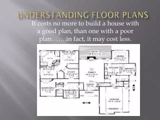
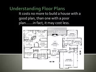
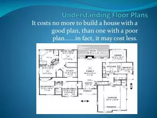
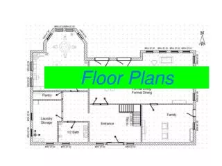
Introduction • The floor plan is the heart of a set of construction drawings • Not a typical top view but a section drawing • Keep the floor plan clean and uncluttered
Walks, patios, and decks Room names Material symbols Location and size dimensions Drawing scale Required Information • Exterior/interior walls • Size and location of windows and doors • Built-in cabinets and appliances • Permanent fixtures • Stairs • Fireplaces
Location and Size of Walls • Draw walls accurately • Avoid variations in wall thickness • Use proper hatch patterns for materials
Location and Size of Windows and Doors • Centerlines locate window and door openings • Centerline not needed in masonry construction • Window opening size = actual sash width • Door opening size = actual door width • Indicate door swing • Draw sills for windows and exterior doors
Location and Size of Windows and Doors • Windows and doors are located in a frame wall with a centerline. Door swing is also shown.
Cabinets, Appliances, and Permanent Fixtures • Show kitchen cabinets, bath vanities, fixtures, and appliances • Use standard symbols at proper scale • Check local code for clearances
Stairs and Fireplaces • Show basic size and location • Stairs—direction of flight, number of risers, width of stairs • Fireplace — either simplified or detailed symbol, basic depth and width, opening design, location
Walks, Patios, and Decks • Outside features included • Walks • Patios • Decks • Swimming pools • Indicate size and materials on plan • Considered as part of total plan
Room Names and Material Symbols • Room names 3/16" high and placed in center of room • Material symbols or material hatch patterns denote each material • Identify symbols that are not standard
Dimensioning • Size and location of features • Locate dimensions logically • Place dimension figure: • Above dimension line • Parallel to the dimension line • Use consistent termination symbols
Dimensioning • Dimension brick veneer walls to outside of stud wall • Dimension solid masonry walls to outside of wall • Overall dimensions provide total length and width of structure or major parts of structure
Dimensioning • Use notes for information that cannot be represented by dimensions or symbols • Place notes should be at bottom of sheet
Employability • A portfolio is a selection of your work • Include items that show technical skills and level of accomplishment
Scale and Sheet Identification • Scale for residential floor plans is 1/4" = 1'- 0" • Paper size determined by structure size • Number multiple sheets • Sheet 1 of 6, 2 of 6, etc. • Sheet numbers are in lower right-hand corner
Metric System of Dimensioning • Customary inch system is standard in US construction industry • Metric system of measurement is standard in most countries outside United States
Drawing a Floor Plan • Determine requirements of structure • Record them as preliminary sketches • Consider expansionfloorplans
Manual Drafting: Floor Plan 1. Lay out exterior walls 2. Locate interior walls 3. Locate windows and doors 4. Draw stairs 5. Draw fireplace 6. Draw walks, patios, and decks
Manual Drafting: Floor Plan 7. Draw kitchen cabinets, appliances, bathroom fixtures 8. Add dimensions, notes, room names 9. Add material and identification symbols 10. Draw title block and add scale 11. Check entire drawing for accuracy and completeness
Architecture Green • Designing a green floor plan • Incorporate eco-friendly design decisions • Design rooms for multiple uses • Centrally locate the heating, ventilation and cooling systems
CADD: Floor Plan 1. Prepare a space diagram 2. Draw exterior and interior walls 3. Add window and door symbols 4. Draw stairs on separate layer 5. Draw or insert fireplace 6. Locate and draw walks, patios, porches
CADD: Floor Plan 7. Draw kitchen cabinets, appliances, and bathroom fixtures 8. Add dimensions on separate layer 9. Add room names, notes, material symbols, drawing scale, drawing title 10. Check entire drawing for accuracy and completeness