Download

1 / 14
230 likes | 397 Views
Refrigeration System Design and Analysis. Brent Cullimore C&R Technologies. Background. Background Vapor compression (V/C) systems are well established in the Automotive industry and HVAC, but are still emerging in thermal management of electronics

E N D
Refrigeration SystemDesign and Analysis Brent CullimoreC&R Technologies
Background • Background • Vapor compression (V/C) systems are well established in the Automotive industry and HVAC, but are still emerging in thermal management of electronics • Modeling of V/C systems is only a few years old • In Automotive, driven by the need to meet EPA mileage/emissions standards: must use transient drive cycles as design criteria • Modeling helps address perpetual concerns such as start-up slugs, oscillations, oil and charge migration upon shut down, etc. • Purpose of this paper: • Share modeling “lessons learned” from Ford, Visteon, GM, Delphi, Danfoss, etc.
Compressor, throttle performance Conserve loop charge Pressure prediction Track liquid and vapor in evaporator and condenser Overall loop energy balance Two-phase heat transfer Fundamental“Lesson Learned” • Self-determination of pressure requires tracking refrigerant mass: full thermohydraulic solution required! Solve for pressures, qualities, temperatures, flow rates, heat transfer coefficients simultaneously
Example:Parametric Sweep • System Description • R134a working fluid • Air-cooled condenser (100ºF environment) • Rotary compressor (defined by performance maps) • Capillary tube throttle (0.030” x 10 ft) • with regenerative suction tube heat exchanger • Vary compressor RPM from 1000 to 3000 • Requires 800W to 1500W input power
Results:Compressor Exit Pressure Constant Inlet Pressure (Different systems!) Constant Charge Mass (Apples to apples!)
Cause of Difference Constant Inlet Pressure 7% increase in charge causes increased liquid “blockage” in condenserand evaporator
Solution:Generalized Thermal/fluid Analyzer SINDA/FLUINT Network Example
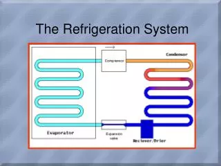
Example:Heat Exchanger Modeling to compressor or dryer from expansion device Evaporator (R134a) Aluminum Heat Exch. Air Side air andcondensate out moist air in
Example:CAD-based Condenser Model Mix and Match Methods Condenser: 1D finite difference/volume thermohydraulics Pipe walls: 2D finite difference thermalFins: 2D finite element thermalAir flow: 1D finite difference network Full parametric modeling
Layers of the“Computational Onion” • Pseudo-steady thermaland thermohydraulics (t ~ 10 min.) • Steady hydraulics,unsteady thermal (t ~ 1 min.) • Mass/energy storagewithout flow inertia (t ~ 10 sec.) • Flow inertia w/omass/energy storage (t ~ 1 sec.) • Mass/energy and inertia,homogeneous equilibriumtwo-phase (t ~ 1 sec.) • Nonhomogeneous equilibriumtwo-phase (t ~ 1 sec.) • Nonhomogeneous nonquilibriumtwo-phase (t ~ 0.1 sec.)
Vliq = Vvap, Tliq = Tvap Vliq < Vvap, Tliq = Tvap Vliq < Vvap, Tliq < Tvap Two-phase Flow:What phenomena are important? • Homogeneous Equilibrium Flow • Phases at same temperature, same velocity • Flow regime mapping optional • Often adequate for VC cycles • Equilibrium Slip Flow • Phases at same temperature, different velocities • Flow regime information required • Enhances accuracy in VC cycles(better void fraction estimation) • Nonequilibrium Slip Flow (“two fluid”) • Phases at different temperatures and velocities • Usually not needed except for severe transientsand high frequency instabilities or control systems
Comparisons with Test:Using Equilibrium Slip Flow • From: “Improvements in the Modeling and Simulation of Refrigeration Systems: Aerospace Tools Applied to a Domestic Refrigerator,” Ploug-Sorensen et al. Danfoss, 1996. Cabinet Temperature Hi/Lo Pressures
Conclusions • Charge mass must be conserved in transients, parametric sweeps, sensitivity studies, etc. • Component-level approaches (effectiveness, average coefficients, etc.) are not suitable:limited to concept-level trade studies • Finite difference/volume subdivision of condenser and evaporator is suitable: tracks mass and “blockage” effects • Two-phase flow is not amenable to CFD approaches • but flow network modeling (FNM) is well suited for the task • Slip flow has been shown to improve accuracy, but full nonequilibrium nonhomogeneous (“two fluid”) modeling is usually not necessary