Download
1 / 30
350 likes | 720 Views
Groundwater Hydrology. Hydrology and Water Resources RSGIS Institute of Space Technology Jan 07, 2014. Groundwater (GW). Groundwater: A component of Hydrologic Cycle Comprises more than 97% of all freshwater on the earth (not considering water trapped in glaciers and icecaps)

E N D
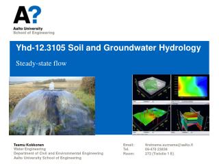
Groundwater Hydrology Hydrology and Water Resources RSGIS Institute of Space Technology Jan 07, 2014
Groundwater (GW) Groundwater: A component of Hydrologic Cycle Comprises more than 97% of all freshwater on the earth (not considering water trapped in glaciers and icecaps) Globally more than one-half of the world’s population depends on groundwater Occurring in the saturated zone of a soil profile Moves very slowly Sometimes difficult to extract Problem associated with GW are: contamination, deep pumping may become uneconomical
Groundwater Hydrology Groundwater hydrology is important in the field of surface water flood hydrology Soil properties and rate of infiltration affect the proportions of rain fall as surface runoff and groundwater losses Thus soil properties affect surface water hydrologic designs
Water Movement in Soil When soil pores filled with water gravity dominates When field capacity is exceeded water starts flowing down
GW Terms • Aquifer • Water bearing porous soil or rock strata that yields significant amount of water to wells • Aquiclude • Water bearing soil or rock strata that are effectively impermeable, such as clay, shales, slates, etc. • Aquitard • Rocks that are poorly permeable (silt and mudstone) • Water Table • Undulating plane below the ground surface at which GW water pressure is equal to atmospheric (also dividing line between saturated and unsaturated zone)
Confined and Unconfined Aquifers Aquifers that contain water that is in direct contact with the atmosphere through porous material are called unconfined aquifers A confined aquifer is separated from atmosphere by an impermeable layer or aquiclude An unconfined aquifer can become a confined aquifer at some distance from the recharge area Confined aquifers, also called artesian aquifers, contain water under pressure Water pressure (P), or pressure potential, is a function of the height of the water column at a point (hp), the density of water (ρ), and the force of gravity (g) P = ρ g hp =γ hp
Confined and Unconfined Aquifers In confined aquifers, the elevation of the water surface measured by wells can be used to construct a water table contour map The piezometric, or potentiometric, surface of an artesian aquifer describes the imaginary level of hydraulic head to which water will rise in wells drilled into the confined aquifer The direction of groundwater flow, or flow lines, can be determined by constructing lines perpendicular to the water table contours from higher to lower elevation contours The potentiometric surface declines because of friction losses between points When the land surface falls below the potentiometric surface, water will flow from the well without pumping (artesian or flowing well)
Springs Where GWT intersects the topography or ground surface, springs are formed
Aquifer Characteristics The amount of water stored or released from a water bearing strata depends on porosity, the size of pore spaces, and the continuity of pores Therefore, mapping the GW Flow is not Easy!
Aquifer Characteristics Porosity: total void space between the grains that can be filled with water (defined as % pore space) Porosity (n)= 100Vv/Vt Where: Vv= volume of void space in a unit volume of rock/soil Vt= total volume of earth material including void space Effective Porosity: ratio of the void space through which water can flow to the total volume If pores are of sufficient size and interconnected to allow water to move freely, the soil or rock is permeable
Aquifer Characteristics Hydraulic Conductivity: velocity of flow through a porous medium resulting from 1 unit of energy head (m/d) (ability of a porous media to transmit water) Transmissivity (m2/unit time): amount of water that can flow horizontally through the entire saturated thickness of the aquifer under the hydraulic gradient of 1m/m Tr = bkv Where: Tr =transmissivity (m2/unit time) b = saturated thickness (m) kv= hydraulic conductivity of the aquifer (m/unit time)
Examples of Hydraulic conductivity From Brooks
Aquifer Characteristics Storativity : volume of water that is either stored or released from a saturated aquifer per unit surface area per unit change in head (unit less) Specific yield: ratio of the volume of water that can drain freely from the saturated earth material due to the force of gravity to the total volume of the earth material
Storativity of confined aquifer Specific Yield
Aquifer Characteristics It is not possible to measure GW velocities within an aquifer Observation piezometers (boreholes) are constructed to determine the elevation of the water level in piezometer The GW head in an aquifer is the height to which water will rise in a piezometer GW head gradients can be used to estimate magnitude and direction of GW velocities The amount of water discharged from an aquifer can be approximated with Darcy’s law
Darcy Law: Flow through a Porous Medium Darcy law states: “ specific discharge in a porous medium is in the direction of decreasing head and directly proportional to the hydraulic gradient” Darcy performed a series of experiments on water flow through columns of sand He packed sand in iron pipes and systematically measured the parameters that he expected to impact the flow Darcy found that the total discharge Q varies in direct proportion to X-sectional area of the column, hydraulic head difference at each end of the column, and inversely with length of column
Darcy Equation Q = KA (h1-h2)/L K = hydraulic conductivity
Darcy Equation Darcy equation can be rewritten as: Q/A = -K (h2-h1)/L V= Q/A = -K (h2-h1)/(l2-l1) This can be written more generally as: q = -K (dh/dl) Where: q = Q/A is the specific discharge (dh/dl) = Hydraulic gradient Negative sign indicates that positive specific discharge (indicating direction of flow) correspond with a negative hydraulic gradient Go back to Darcy’s Law and now try to understand
The Darcy velocity is an average discharge velocity through the entire x-section of the column, the actual flow is limited to the pore channels only The seepage velocity Vs is equal to the Darcy velocity divided by porosity Vs = Q/nA Actual seepage velocities are therefore much higher (by a factor of 3) than the Darcy velocities
Example Darcy’s Law Determine the discharge of flow through a well sorted gravel aquifer. The change in head is 1 m over the distance of 1,000 m and the cross-sectional area of the aquifer is 500 m2. find Q? Q = K A dh/dL Q = (0.01 cm/sec ) (500 m2) (0.001 m/m) (0.01 m/cm) Q = 0.00005 m3/sec or 4.32 m3/d
Groundwater Development Assessing groundwater potential for GW development requires knowledge of the local geology and aquifers Surface features ordinarily does not indicate any sign related to the location, depth, and extent of water bearing material or strata Geological maps can be used to help identify potentially productive water bearing strata by examining the direction and degree of dipping strata, locating faults and fracture zones, and determining the stratigraphy of rocks with different water bearing and hydraulic characteristics As a rule, opportunities for GW development increase as one moves from upland watersheds to lower basins and floodplains Extensive and high yielding aquifers occur in the most major river valleys and alluvial plains
Well • A vertical hole dug into the ground • Many types of wells • Well Point • Lower end of pipe • Cone of depression • Created by pumping water from well that lowers the water table around the well • Drawdown • The difference between original water level and the water level after a period of pumping • Discharge rate is measured through flow meter attached to the discharge pipe • Interference • Locating wells too close together causing more lowering of a water table than spacing them far apart
Management of Groundwater Resources Means controlled use in accord with some plan Continued extraction of GW may create many problems Use of GW without consideration to its effects is unwise Good management is to minimize the adverse effects of GW use with good knowledge of the probable effect Need to know local area GW conditions (including quality) and basic research on recharge and movement of GW is required GW can be managed using the concept of safe yield Safe Yield: The rate of water that can be extracted from an aquifer during anytime period that do not produce undesirable effects (excessive lowering of water table, saltwater intrusion, high pumping cost)
GW Management (sustained withdrawal of GW) Water budget analysis to study quantitative aspects of safe yield I – O = ΔS Where I = inputs to GW (including GW recharge by percolation of rainwater and snowmelt, artificial recharge through wells, and seepage from lakes and streams) O = output from GW (including pumping, seepage to lakes and streams, springs, etc. Δ S = change in storage
GW Recharge • Natural • Artificial • Induced infiltration, spreading, recharge wells • Water moves through aquifer under the influence of gravity, therefore the zone of recharge should be higher than areas of discharge
GW software • http://water.usgs.gov/software/lists/groundwater/ • MODFLOW • GMS (http://www.aquaveo.com/gms?gclid=CJ-i-YO40qYCFRIRfAodDhH4gA ) • GMS is a comprehensive groundwater modeling environment with GIS based graphical preprocessing tools to automate and streamline the modeling process. GMS seamlessly interfaces with MODFLOW and several other preeminent groundwater models, and provides advanced graphical features for viewing and calibrating model results.