Download
1 / 11
140 likes | 832 Views
Quasi-Passive Cyclic DAC. Gabor C. Temes School of EECS Oregon State University. Outline. Quasi-Passive Cyclic DAC Operation Capacitor Mismatch and Mismatch Compensation Capacitor mismatch Mismatch c ompensating s witching Spectrum shaping Radix-based d igital c orrection

E N D
Quasi-Passive Cyclic DAC Gabor C. Temes School of EECS Oregon State University
Outline • Quasi-Passive Cyclic DAC • Operation • Capacitor Mismatch and Mismatch Compensation • Capacitor mismatch • Mismatch compensating switching • Spectrum shaping • Radix-based digital correction • Two-Capacitor DAC Enhancements • Time interleaved 2-C DACs • Pipelined quasi-passive cyclic DAC 1/10
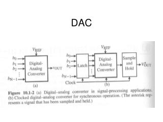
Quasi-Passive Cyclic DAC • Operation: • Charge redistribution between two equal-valued capacitors • Serial digital input; LSB first • Φ1 and Φ2 are two non-overlapping clock phases • Conversion follows equation DAC basic architecture [1] R. E. Suarez et al., “All-MOS charge distribution analog-to-digital conversion techniques – Part II,” JSSC, Dec. 1975, pp. 379-385. Conversion sequence for input ‘1101’ 2/10
Capacitor Mismatch • Capacitor mismatch effects • Conversion accuracy limited by capacitor matching • Capacitor mismatch introduces nonlinearity • Plots show performance degradation (bottom) in SNDR and SFDR compared with output spectrum from DAC with ideal matching (top) 3/10
Mismatch Compensation (1) • Switching techniques • Compensative switching • The roles of the two capacitor is interchangeable • The roles of the capacitors can be chosen on bit-wise base • An algorithm was developed to minimize the conversion error for any digital word • The switching pattern is input dependent • First-order error canceled for 31% of the input codes; reduced to 1/10 for 48% of the input codes The roles of the two capacitors are interchangeable with additional switches [2] Weyten, L.; Audenaert, S., "Two-capacitor DAC with compensative switching," Electronics Letters , vol.31, no.17, pp.1435-1437, 17 Aug 1995. 4/10
Mismatch Compensation (2) • Switching techniques • Complementary switching • Digital word fed to 2-C DAC twice; once with normal arrangement, once with swapped roles of C1 and C2 • Output softhe two conversions are added (or averaged) • First-order mismatch compensated at costof doubled conversion time [3] Rombouts, P.; Weyten, L., "Linearity improvement for the switched-capacitor DAC," Electronics Letters , vol.32, no.4, pp.293-294, 15 Feb 1996. 5/10
Mismatch Compensation (3) • Switching techniques • Input-word-splitting compensative switching • Compensative switching [2] does not compensate for all input codes • Split digital input into sum of two digital codes • The conversion errors need to be able to be respectively compensated using compensative switching for the two new digital inputs • Final output is the sum of the two conversions • Needs two sets of 2-C DACs • Needs analog summation • Needs sophisticated algorithm for splitting the input word [4] Rombouts, P.; Weyten, L.; Raman, J.; Audenaert, S., "Capacitor mismatch compensation for the quasi-passive-switched-capacitor DAC," Circuits and Systems I: Fundamental Theory and Applications, IEEE Transactions on , vol.45, no.1, pp.68-71, Jan 1998. 6/10
Mismatch Compensation (4) • Switching techniques • Alternately complementary switching • Roles of C1 and C2 are swapped alternately in the first cycle and adopt complementary switching [3] for the second conversion cycle • Output of the two conversions are summed (or averaged) • INL improved due to cancellation of major second-order error • Hybrid switching • Averaging conversion results of complementary switching and alternately complementary switching • Smaller INL; fourfold conversion cycles [5] Poki Chen; Ting-Chun Liu, "Switching Schemes for Reducing Capacitor Mismatch Sensitivity of Quasi-Passive Cyclic DAC," Circuits and Systems II: Express Briefs, IEEE Transactions on , vol.56, no.1, pp.26-30, Jan. 2009 7/10
Mismatch Compensation (5) • Mismatch shaping • Using oversampling ΔΣ Modulator • Digital state machine to control switching sequence of a symmetric two-capacitor DAC • Improved linearity; better shaping for higher OSR • Needs 2N clock cycles for N-bit D/A [6] Steensgaard, J.; Moon, U.-K.; Temes, G.C., "Mismatch-shaping serial digital-to-analog converter," Circuits and Systems, 1999. ISCAS '99. Proceedings of the 1999 IEEE International Symposium on , vol.2, no., pp.5-8 vol.2, Jul 1999 Simulated (FFT) performance of the DAC without (a) and with (b) mismatch shaping using a second-order loop filter 8/10
Mismatch Compensation (6) • Radix-Based Digital Correction • Compensation in digital domain • Effectively a radix-(C1/C2) conversion • Assumes known mismatch 2(C1-C2)/(C1+C2), or C1/C2 • ADC-like algorithm predistortsdigital input • Feeds predistorteddigital words into the 2-C DAC • Better performance when DAC resolution is high • Need to find mismatch with high accuracy Radix-based digital pre-distortion algorithm flowchart DAC output spectra plots for (a) uncompensated condition, (b) alternately complementary switching, (c) radix-based algorithm and (d) radix-based algorithm with one extra bit. 9/10
Two-Capacitor DAC Variations • Time interleaved 2-C DAC • Time interleaving 2-C blocks improves throughput speed • Capacitor mismatch among channels tolerable • Direct-charge-transfer buffer reduces power consumption • Pipelined quasi-passive cyclic DAC • Same operation as 2-C DAC • Information passed on to the last capacitor and DCT output buffer [7] Wang, F.-J.; Temes, G.C.; Law, S., "A quasi-passive CMOS pipeline D/A converter," Solid-State Circuits, IEEE Journal of , vol.24, no.6, pp.1752-1755, Dec 1989 10/10