Download
1 / 132
1.67k likes | 2.45k Views
Computer Graphics & Image Processing Lecture 3 Image Enhancement in Spatial Domain. ALI JAVED Lecturer SOFTWARE ENGINEERING DEPARTMENT U.E.T TAXILA Email:: alijaved@uettaxila.edu.pk Office Room #:: 7. Image Enhancement.

E N D
Computer Graphics & Image Processing Lecture 3 Image Enhancement in Spatial Domain
ALI JAVED Lecturer SOFTWARE ENGINEERING DEPARTMENT U.E.T TAXILA Email:: alijaved@uettaxila.edu.pk Office Room #:: 7
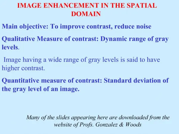
Image Enhancement Process an image to make the result more suitable than theoriginal image for a specific application –Image enhancement is subjective (problem /application oriented) Image enhancement methods: Spatial domain: Direct manipulation of pixel in an image (on the image plane) Frequency domain: Processing the image based on modifying the Fourier transform of an image Many techniques are based on various combinations of methods from these two categories
Basic Concepts Spatial domain enhancement methods can be generalized as g(x,y)=T[f(x,y)] f(x,y): input image g(x,y): processed (output) image T[*]: an operator on f (or a set of input images), defined over neighborhood of (x,y) Neighborhood about (x,y): a square or rectangular sub-image area centered at (x,y)
Basic Concepts g(x,y) = T [f(x,y)] Pixel/point operation: Neighborhood of size 1x1: g depends only on f at (x,y) T: a gray-level/intensity transformation/mapping function Let r = f(x,y) s = g(x,y) r and s represent gray levels of f and g at (x,y) Then s = T(r) Local operations: g depends on the predefined number of neighbors of f at (x,y) Implemented by using mask processing or filtering Masks (filters, windows, kernels, templates) : a small (e.g. 3×3) 2-D array, in which the values of the coefficients determine the nature of the process
3 basic gray-level transformation functions • Linear function • Negative and identity transformations • Logarithm function • Log and inverse-log transformation • Power-law function • nth power and nth root transformations
Identity Function Output intensities are identical to input intensities. Is included in the graph only for completeness. 9
Image Negatives • Reverses the gray level order • For L gray levels the transformation function is s =T(r) = (L - 1) - r
Log Transformations Function ofs = cLog(1+r)
Log Transformations Properties of log transformations –For lower amplitudes of input image the range of gray levels is expanded –For higher amplitudes of input image the range of gray levels is compressed Application: • This transformation is suitable for the case when the dynamic range of a processed image far exceeds the capability of the display device (e.g. display of the Fourier spectrum of an image) • Also called “dynamic-range compression / expansion”
Inverse Log Transformations Do opposite to the Log Transformations Used to expand the values of high pixels in an image while compressing the darker-level values. 14
Power-Law Transformation For γ < 1: Expands values of dark pixels, compress values of brighter pixels For γ > 1: Compresses values of dark pixels, expand values of brighter pixels If γ=1 & c=1: Identity transformation (s = r) A variety of devices (image capture, printing, display) respond according to power law and need to be corrected Gamma (γ) correction The process used to correct the power-law response phenomena
Gamma correction Monitor = 2.5 Gamma correction Monitor =1/2.5 = 0.4 • Cathode ray tube (CRT) devices have an intensity-to-voltage response that is a power function, with varying from 1.8 to 2.5 • The picture will become darker. • Gamma correction is done by preprocessing the image before inputting it to the monitor with s = cr1/
Piecewise-Linear Transformation Contrast Stretching Goal: • Increase the dynamic range of the gray levels for low contrast images Low-contrast images can result from –poor illumination –lack of dynamic range in the imaging sensor –wrong setting of a lens aperture during image acquisition
Piecewise-Linear Transformation: Gray-level slicing • Highlighting a specific range of gray levels in an image • Display a high value of all gray levels in the range of interest and a low value for all other gray levels • (a) transformation highlights range [A,B] of gray level and reduces all others to a constant level • (b) transformation highlights range [A,B] but preserves all other levels 23
Piecewise-Linear Transformation: Bit Plane slicing Bit-plane 7 (most significant) One 8-bit byte Bit-plane 0 (least significant) • Highlighting the contribution made to total image appearance by specific bits • Suppose each pixel is represented by 8 bits • Higher-order bits contain the majority of the visually significant data • Useful for analyzing the relative importance played by each bit of the image 24
8 bit planes 25
Contrast Stretching through Histogram If rmax and rmin are the maximum and minimum gray level of the input image and L is the total gray levels of output image The transformation function for contrast stretching will be
Histogram Equalization • Spreading out the frequencies in an image (or equalising the image) is a simple way to improve dark or washed out images • The formula for histogram equalisation is given where • rk: input intensity • sk: processed intensity • k: the intensity range (e.g 0.0 – 1.0) • nj: the frequency of intensity j • n: the sum of all frequencies 34
Histogram Equalization: Example Image After Equalization Initial Image 36 Notice that the minimum value (52) is now 0 and the maximum value (154) is now 255.
No. of pixels 6 5 4 3 2 1 Gray level 4x4 image 0 1 2 3 4 5 6 7 8 9 Gray scale = [0,9] histogram Histogram Equalization: Example 38
No. of pixels 6 5 4 3 2 1 Output image 0 1 2 3 4 5 6 7 8 9 Gray scale = [0,9] Gray level Histogram equalization Histogram Equalization: Example 40
Mathematical/Logical Operations on Images • Addition –Averaging images for noise removal • Subtraction –Removal of background from images –Image enhancement –Image matching –Moving/displaced object tracking • Multiplication –Superimposing of texture on an image –Convolution and correlation of images • And and or operations –To remove the unnecessary area of an image through mask operations
Image Subtraction • Takes two images as input and produces a third image whose pixel values are those of the first image minus the corresponding pixel values from the second image • Variants • It is also often possible to just use a single image as input and subtract a constant value from all the pixels • Just output the absolute difference between pixel values, rather than the straightforward signed output.
Image Subtraction • The subtraction of two images is performed in a single pass • If the operator computes absolute differences between the two input images then: • If it is simply desired to subtract a constant value C from a single image then:
Image Subtraction • If the operator calculates absolute differences, then it is impossible for the output pixel values to be outside the range • In rest of the two cases the pixel value may become negative • This is one good reason for using absolute differences. • How to solve problem of negative pixels?
Image Subtraction • How to solve problem of negative pixels? • Let we have an 8 bit Grayscale image (Value Range= 0 t0 255) • The result of image subtraction may come in the range of -255 to +255 • One scheme can be to add 255 to every pixel and then divide by 2 • Method is easy and fast • Limitations • Truncation errors can cause loss of accuracy • Full range of display may not be utilized
Image Subtraction • How to solve problem ofNegative Pixels? • Another scheme can be • first, find the minimum gray value of the subtracted image • second, find the maximum gray value of the subtracted image • set the minimum value to be zero and the maximum to be 255 • while the rest are adjusted according to the interval [0, 255], by timing each value with 255/max