Download
1 / 29
290 likes | 391 Views
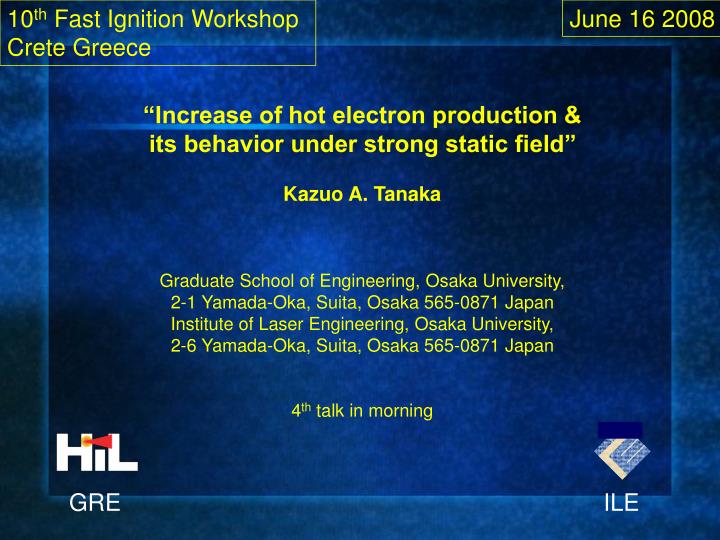
10 th Fast Ignition Workshop Crete Greece. June 16 2008. “Increase of hot electron production & its behavior under strong static field” Kazuo A. Tanaka Graduate School of Engineering, Osaka University, 2-1 Yamada-Oka, Suita, Osaka 565-0871 Japan

E N D
10th Fast Ignition Workshop Crete Greece June 16 2008 “Increase of hot electron production & its behavior under strong static field” Kazuo A. Tanaka Graduate School of Engineering, Osaka University, 2-1 Yamada-Oka, Suita, Osaka 565-0871 Japan Institute of Laser Engineering, Osaka University, 2-6 Yamada-Oka, Suita, Osaka 565-0871 Japan 4th talk in morning GRE ILE
Co-authors. • Endo, K.1), 2), Habara, H.1), 2) , Honda S.1), 2), Katayama M.1), 2),Kumar, R. G.3), Kodama, R.1), 2), Krushelnek, K.4), Lei, A. L.5),Matsuoka, T.4), Mima, K.1), Nakamura, T.1), 2),Nagai, K.1), Norimatsu, T.1), Sentoku, Y.6) ,Tanimoto, T.1), 2), Yabu-uchi, T.1), 2) • 1) Graduate School of Engineering, Osaka University, Suita, Osaka 565-0871Japan • 2 Institute of Laser Engineering), Osaka University, Suita, Osaka Japan • 3) Tata Institute of Fundamental Research, Mumbai, India • 4) University of Michigan, Center for Ultrafast Optical Science, MI USA • 5) Shanghai Institute of Optics and Fine Mechanics, Shanghai, China • 6) Department of Physics, University of Nevada, Nevada U.S.A
My presentation will include • Foam or low density target can increase the coupling efficiency for hot electrons. • Hot electrons are subject to strong E & B fields when they leave a target.
Introduction • Gold cone was used to guide a fast heating laser pulse in order to heat a highly compressed plasma core up to 1 keV. • 30 % coupling efficiency was indicated in the experiment from the heating laser to the core. Based on this high efficiency 10 kJ PW laser is now under construction to test even higher fast heating temperature up to several keV at the Inst. Laser Engineering. This should be close to fast ignition. • Important issues are to understand the physics of this high efficiency, to increase further the efficiency and to study the both electro-static potential formation at around the target affecting on the relativistic hot electron energy transport.
Compression and heating can be separated in fast ignition. ILE Osaka Compression by multiple laser beams Heating by ultra-intense laser pulse Ignition & Burn
Gold foam inside the cone • To increase the heating efficiency of the core plasma, we propose a foam cone-in-shell target design. Gold cone with inner tip covering with a foam layer Relativistic laser Fuel shell Multiple implosion beams
Element experiment demonstration of the improvements of the foam-in-shell target design for fast ignition • ILE target group are now fabricating the foam cone and foam cone-in-shell target. • We used planar targets in the element experiments. Planar configuration does not change the physics behind the cone tip. • -to measure –e yield • -to measure –e temperature • -to measure –e beam divergence
Element experiment 1:monitoring the heating of the target rear and measuring –e energy spectra • Target types: 20um Mo with front surface coating with 2mm thick solid Au or 2mm thick 20% solid density Au foam • -micro-structured targets (nanoparticles, foams, etc) experimentally demonstrate high laser absorption. Expected more hot electrons generated. • -gold foam used: (expected) to avoid severe suppression of hot –e transport in high-Z thin foam. • Planar targets used gold foam material K. Nagai et al., Fusion Sci. & Tech. 49, 686 (2006)
For target heating and hot e- yield Front XPHC Back XPHC Target For –e energy spectra ESM GXII PW laser Element experiment 1:monitoring the heating of the target rear and measuring –e energy spectra • Experimental setup: • -GXII PW laser: ~0.6ps/1.053um/~100J on targets/~70um focus/OPCPA 10-8 contrast ratio/f7.6/p-pol/26deg incidence • -planar targets: 2um Au+20um Mo, and 2um Au foam+20um Mo • -front XPHC: 18um size pinhole/40um Be filter/KeV x-ray range/M=~8.6 • -back XPHC: 200um size pinhole/40um Be/KeV x-ray range • -ESM: along the laser axis, energy range 1~100MeV.
Au foam coating enhances laser absorption and hot electron generation • Hot -e yield measurement via the back x-ray emission from the target rear due to the heating from hot –e beams • -weak front x-ray emission from the Au foam-coated target. This is due to the low density of the foam. • -stronger back x-ray emission from the Au foam coated target. This is attributed to higher laser absorption and more hot electrons generated with the foam coated target. Back x-ray emission is caused by the hot –e beam heating of the target rear. • -target is thick so that the front x-ray emission may not be responsible for the enhancement of back x-ray emission with foam coated target. Moreover, if it happens, one would expect weak x-ray emission from the foam coated target rear, contrary to the experimental results. • -narrow band-width x-ray image diagnostics needed to give the relative hot –e yield through assuming Plankian emission from the target rear. • -quantitative models and simulations needed
Au foam coating does not change the hot – electron energy spectral characteristics • Hot -e energy spectra are very similar for solid gold coated and gold foam coated targets, showing a temperature ~1.5MeV, a typical value for solid aluminum targets • There is a question: why there is no comparable increase in the amount of hot electrons observed with Au foam coated target? • In vacuum electrons escaping from the target is fully limited by the static potential. • [T. Yabu-uchi et al., submitted to Phys. Rev. E.]
Carbon nano tubes are grown on Ta target by CVD. CVD: Electron beam deposition make Fe/Al layer on surface. The surface is treated by CVD with He /acetylene (gas). at 650 degrees. Collaboration with Prof. M. Katayama’s laboratory Osaka University. SEM photo of CNT grown normal to surface. 1010 CNT/cm2.
Laser Power:30TW Int.:> Pulse Width:30fs Wavelength:800nm Ultra-intense laser irradiates carbon nano tube on Ta substrate. Target Target CNT (Length 60um、SubstrateTa 10umt) W (35umt) Incident Laser g-ray detector X-ray diode Diagnostics X-ray diode:monitor x-ray emission NaIScintilator:monitor g-ray emission. Collaboraiton w/ CUOS Michigan
Carbon nano tube is irradiated at 1019 W/cm2 indicating increase of hot electron generation. Gamma ray Intensity (mV/TW/mm) X-ray Intensity (mV/TW/mm)
Laser Intensity:> Energy:10J Pulse :1ps Wavelength:1053nm Electron spectrum and spatial distribution are measured of CNT. Target CNT (Length40um、SubstrateTa 10umt) Al (10umt) Diagnostcis ESM : monitor electron spectrum Stack : monitor electron & proton spatial distribution. X-ray pinhole camera:monirot x-rays. Interferometer: monitor prepulse. (兒玉研究室提供) Experiment@ GM2
Spatial distribution of e-hot from CNT. Spatial distribution of e-hot from plane Al. CNT electrons are strongly scattered by Ta. E hot scattered angle Particle Number Angle Simulated scattered angle on Al & Ta.
Electron spectrum for CNT- Ta target Electron/MeV/Sr Energy (MeV)
E & B fields formation also strongly affect electron behaviors. Intense laser creates MV/mm E and tens of MGauss B fields at the target rear.
Target rear plasma is created using another laser beam to control the rear sheath potential.
Retardation time is determined with rear plasma capacity. nplasma = lNmax [mm/cm3] :Total Number Electr. . nhot= c Ncmax [mm/cm3s]: Hot Electr. Flux Total No. Electr. Tretard. = Hot Electr. Flux.
100-150 fs Delay 1-D PIC shows retardation of potential growth for rear plasma case.
Net electron increase of factor 2-3 consistent with Alfven limit.
Summary • Au foam target increased a plane target heating efficiency.A.L.Lei, K.A. Tanaka et al., Phys. Rev. Lett., 96, 255006(2006). • Carbon nano tube appears to increase the laser-hot electron coupling. • Electro-static potential formation is studied to understand hot electrons leaving from a target.T. Yabu-uchi, K.A. Tanaka et al., Phys. Plasmas 14, 040706 (2007)
PIC shows clear difference of E field formation. wo/rear plasma w/rear plasma