Download
1 / 14
140 likes | 253 Views
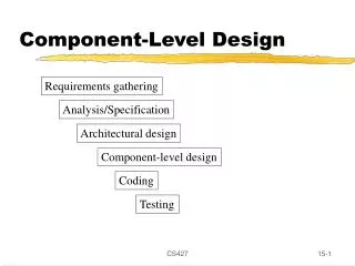
HW/SW Co-design. Lecture 5: Lab 3 – Active HW Accelerator Design. Course material designed by Professor Yarsun Hsu, EE Dept, NTHU RA: Yi-Chiun Fang, EE Dept, NTHU. Outline. Active Hardware Design Co-designed System on FPGA. ACTIVE HARDWARE DESIGN. Active Hardware.

E N D
HW/SW Co-design Lecture 5: Lab 3 – Active HW Accelerator Design Course material designed by Professor Yarsun Hsu, EE Dept, NTHU RA: Yi-Chiun Fang, EE Dept, NTHU
Outline • Active Hardware Design • Co-designed System on FPGA
Active Hardware • Most devices in the real world have the ability to actively generate interrupts • When the CPU detects that an interrupt is asserted, it saves a small amount of state and jumps to the kernel interrupt handler at a fixed address in memory • The handler performs the corresponding processing (ISR), and executes a “return from interrupt” instruction to return the CPU to the execution state prior to the interrupt
GRLIB IRQMP (1/2) • Multiprocessor Interrupt Controller • Attached to AMBA bus as an APB slave • The interrupts generated on the interrupt bus are all forwarded to the interrupt controller • The interrupt controller prioritizes, masks and propagates the interrupt with the highest priority to the processor
GRLIB IRQMP (2/2) • IRQMP implements a two-level interrupt controller for 15 interrupts • When any of the IRQ lines are asserted high, the corresponding bit in the interrupt pending register is set • The pending bits will stay set even if the IRQ line is de-asserted, until cleared by software or by an interrupt acknowledgefrom the processor
Active 1-D IDCT HW Acc. (1/3) • The data path is identical to its passive version • The registered IRQ number is 15 • HIRQ line raises up for exactly one clock cycle right after the second stage completes Raise HIRQ signal for one clock cycle stage1 stage2 addr phase data phase
Active 1-D IDCT HW Acc. (2/3) • Every time the system is interrupted by the IDCT accelerator, its ISR will set a global variable idct_flag to 1 cyg_uint32 idct_isr(cyg_vector_t vector, cyg_addrword_t data) { unsigned long *idct_flag = (unsigned long *) data; (*idct_flag) = 1; cyg_interrupt_acknowledge(vector); return CYG_ISR_HANDLED; }
Active 1-D IDCT HW Acc. (3/3) • Instead of polling the device registers, we now wait for idct_flag to become 1 • We reset the flag back to 0 afterwards static void hw_idct_1d(short *dst, short *src, unsigned int mode) { ... *c_reg = (long)((mode << 1) | 0x1); while (idct_flag == 0){ /*busy waiting loop*/ } idct_flag = 0; ... }
Build SW Application • In addition to the flags mentioned in the previous labs, we use -D_HW_ACTIVE_ flag to enable the use of IDCT ISR • This flag will only work if -D_HW_ACC_ flag is set • Use make to build the new version
Install IDCT Accelerator • We replace grlib-gpl-1.0.19-b3188/lib/esw/idct_acc/idct_1x8.vhd with lab_pkg/lab3/hw/idct_1x8.vhd • Use make ise | tee ise_log to build the bitstream
Profiling Results (1/2) • Build the program with -D_PROFILING_ flag on • Compare the computation results of sw_idct_2d() and hw_idct_2d() • Compare thecomputationresults withand without-D_HW_ACTIVE_flag
Profiling Results (2/2) • The active version is still faster than the pure SW implementation but much slower than its passive version • Interrupt latency • The calculation is too fast • Only lasts for two clock cycles • The action bit is already reset to 0 when the CPU polls the device registers for the first time • Interrupt is useful when the CPU gets to do other meaningful operations before the hardware completes