Download
1 / 26
260 likes | 406 Views
EET 2261 Unit 11 Serial Communications Interface. Read Almy , Section 24. Homework #11 and Lab #11 due next week. Quiz next week. Interrupts. An interrupt is a mechanism for causing a program to temporarily suspend what it’s doing, and do something else instead.

E N D
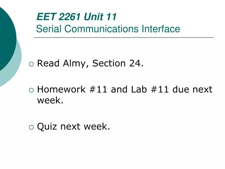
EET 2261 Unit 11Serial Communications Interface • Read Almy, Section 24. • Homework #11 and Lab #11 due next week. • Quiz next week.
Interrupts • An interrupt is a mechanism for causing a program to temporarily suspend what it’s doing, and do something else instead. • Interrupts are commonly used with I/O devices (keyboards, etc.). By using interrupt-driven I/O, a program can efficiently service the I/O devices only when they need attention. • The alternative is polled I/O, in which the program periodically stops what it’s doing and checks to see whether any I/O device needs service.
An Analogy • Suppose you’re at home working on a demanding task (writing a paper), and at the same time you’re waiting for FedEx to deliver an important package. • Two possible approaches: • Get up from your desk every 30 seconds to look out the window for the FedEx truck. • Focus on writing your paper, and let the FedEx driver ring the doorbell to announce her arrival.
An Analogy (Continued) • On this analogy: • Your paper-writing task is like the processor’s main program. • The FedEx delivery is like an I/O device. • The first approach (getting up from your desk every 30 seconds) is like polled I/O. Not a good way to work, is it? • The second approach (relying on the doorbell) is like interrupt-driven I/O. Makes better use of your time!
An Analogy (Continued) • In real life, there may be many different events that could interrupt you from your primary task: • Doorbell • Telephone • Tornado siren • Dog scratching at the door to be let out • Similarly, the HCS12 has many (about 50) different kinds of interrupts that may require the CPU to temporarily set aside its main task. • Some of these interrupts come from outside the HCS12 chip, and some come from circuits on the HCS12 chip itself.
Enabling Interrupts • For most (but not all) of the 50 kinds of interrupts, the programmer can enable or disable the interrupt. If an interrupt is disabled, it will be ignored by the CPU. • We’ll see later that many special function registers hold bits that let the user enable or disable specific kinds of interrupts. • Two bits in the Condition Code Register (CCR) also play a key role in enabling or disabling interrupts….
Figure 11-1 The I and X Bits in the CCR Register Condition Code Register Bits X and I
Interrupt Service Routine • Assuming that interrupts are enabled, when the CPU receives an interrupt signal, it sets aside whatever it is doing and runs code called an interrupt service routine (ISR) or interrupt handler. • The programmer must write these ISRs, which are like subroutines that get called automatically when a interrupt occurs.
Interrupt Vector Table • For each type of interrupt, there is a fixed location in memory into which the programmer must load the starting address of its interrupt service routine (ISR). • The group of memory locations set aside to hold the starting addresses of the ISRs is called the interrupt vector table.
Location of Interrupt Vector Table • Memory locations $FF00 through $FFFF are reserved for the interrupt vector table. • Figure page 26 of Device User Guide.
List of Interrupt Vector Locations • For complete list, see pages 75-76 of the Device User Guide. • The list orders interrupts from highest priority to lowest. (Priority comes into play if two interrupts occur at the same time.)
Resets, Traps, and Interrupts • Of the 50-plus kinds of interrupts, the three highest-priority ones are called resets: • Reset • Clock Monitor Fail Reset • Computer Operating Properly (COP) Reset • The next two highest-priority ones are often called traps: • Unimplemented Opcode Trap • Software Interrupt (SWI) Trap • The rest are just called interrupts.
Info in the Interrupt Vector Table • For each type of interrupt, the table tells us: • The source (name) of the interrupt. • The locations in memory where the programmer must store the starting address of the interrupt’s service routine. • Whether the interrupt can be masked (disabled) by a bit in the Condition Code Register (CCR). • Whether the interrupt can be enabled/disabled somewhere other than the CCR. • Whether the interrupt can be elevated to a higher priority.
Steps in Executing an Interrupt • When the HCS12 receives an interrupt, it follows these steps: • It finishes executing the current instruction. • It pushes the contents of PC, Y, X, A, B, and CCR onto the stack, thus saving a snapshot of exactly what the CPU was doing before it was interrupted. • It fetches the address of the appropriate interrupt service routine (ISR) from the interrupt vector table and places this address in the Program Counter (PC)….
Steps in Executing an Interrupt (Continued) • …It sets the I bit in CCR high to ensure no other interrupt can interrupt the CPU while it’s serving the current one. • It fetches and executes instructions belonging to the interrupt service routine. • The last instruction of the interrupt service routine must be an RTI (Return from Interrupt). • RTI causes the CPU to pull the original PC, Y, X, A, B, and CCR values from the stack, thus restoring the CPU to the state it was in before it serviced the interrupt. • It then continues to run the code from where itleft off before the interrupt.
Interrupts and Special Function Registers • Many of the bits in the chip’s special function registers are devoted to configuring and controlling interrupts. • Most of the bits in these registers are either • enable bits, which we set or reset to decide whether we’re allowing interrupts • or flag bits, which the hardware sets to indicate that an interrupt has occurred. Your interrupt service routine should reset these flags to “clear” the interrupt.
Example 1: Timer Overflow Interrupt • Timer Overflow interrupt: • Enabled or disabled by the TOI bit in TSCR2: • We’re already familiar with the Timer Overflow Flag bit in TFLG2:
Polling Versus Interrupts for Timer Overflows • Your program named Lab9TimerOverflowFlag sat in a tight little loop, polling the TOF bit repeatedly until it was set, at which point the program proceeded to take some other action: • Here: BRCLRTFLG2, %10000000, Here • A better way is to use an interrupt instead of repeatedly polling the TOF bit.
Programming an Interrupt • Programming an interrupt involves several steps on the programmer’s part: • Enable the interrupt (usually by clearing the I bit in the CCR and setting one or more local enable bits). • Write the interrupt service routine (ISR), which is much like a subroutine except it must end with RTI, not RTS. • Place the ISR’s starting address in the appropriate location within the interrupt vector table.
Example: Programming an Interrupt Skeleton of code for using TOF interrupt:
Example 2: Timer Channel Interrupts • Each output compare/input capture channel has its own interrupt: • Enabled or disabled by the bits in TIE: • We’re familiar with the flag bits in TFLG1:
Polling Versus Interrupts for Output Compare/Input Capture • Your programs named Lab9OutputCompare and Lab9InputCapture sat in a tight little loop, polling the C0F bit repeatedly until it was set, at which point the program proceeded to take some other action: • Here: BRCLRTFLG1, %00000001, Here • A better way is to use an interrupt instead of repeatedly polling the C0F bit.
Example 3: Serial Communications Interface (SCI) Interrupt • Each SCI module has its own interrupt, which can be caused by either the receive data register being full or the transmit data register being empty: • Enabled or disabled by TIE and RIE in SCICR2: • We’re familiar with the flag bits in SCISR1:
Polling Versus Interrupts for Serial Communications • Your programs named Lab10SerialTransmit and Lab10SerialReceive sat in a tight little loop, polling the TDRE bit or the RDRF bit repeatedly until it was set, at which point the program proceeded to take some other action: • Over: BRCLR SCI1SR1, %00100000, Over • A better way is to use interrupts instead of repeatedly polling the TDRE bit or the RDRFbit.
Example 4: Port H Interrupts • Port H has its own interrupt, which can be caused by any of the bits in Port H: • Enabled or disabled by the bits in PIEH: • Flag bits are in PIFH:
Polling Versus Interrupts for Port H • Your program named Lab05SwitchesToLEDs sat in a loop, reading the switches and sending the switch values to the LEDs: • Back: LDAAPTHSTAAPORTB BRA Back • A better way is to use an interrupt to tell us when the switch settings have changed, instead of repeatedly polling the switches.