Download
1 / 38
440 likes | 697 Views
Fe-Carbon Diagram, TTT Diagram & Heat Treatment Processes. Produced By:. Behzad Heidarshenas Ph.D in Manufacturing Processes Mechanical Engineering Department. Fe-Carbon Diagram. IRON CARBON CONSTITUTIONAL DIAGRAM-II.

E N D
Fe-Carbon Diagram, TTT Diagram & Heat Treatment Processes Produced By: Behzad Heidarshenas Ph.D in Manufacturing Processes Mechanical Engineering Department
The following phases are involved in the transformation, occurring with iron-carbon alloys: • L - Liquid solution of carbon in iron; • δ-ferrite – Solid solution of carbon in iron. Maximum concentration of carbon in δ-ferrite is 0.09% at 2719 ºF (1493ºC) – temperature of the peritectic transformation. The crystal structure of δ-ferrite is BCC (cubic body centered). • Austenite – interstitial solid solution of carbon in γ-iron. Austenite has FCC (cubic face centered) crystal structure, permitting high solubility of carbon – up to 2.06% at 2097 ºF (1147 ºC). Austenite does not exist below 1333 ºF (723ºC) and maximum carbon concentration at this temperature is 0.83%. • α-ferrite – solid solution of carbon in α-iron. α-ferrite has BCC crystal structure and low solubility of carbon – up to 0.25% at 1333 ºF (723ºC). α-ferrite exists at room temperature. • Cementite – iron carbide, intermetallic compound, having fixed composition Fe3C.
The following phase transformations occur with iron-carbon alloys: • Alloys, containing up to 0.51% of carbon, start solidification with formation of crystals of δ-ferrite. Carbon content in δ-ferrite increases up to 0.09% in course solidification, and at 2719 ºF (1493ºC) remaining liquid phase and δ-ferrite perform peritectic transformation, resulting in formation of austenite. • Alloys, containing carbon more than 0.51%, but less than 2.06%, form primary austenite crystals in the beginning of solidification and when the temperature reaches the curve ACM primary cementite stars to form. Iron-carbon alloys, containing up to 2.06% of carbon, are called steels.
Alloys, containing from 2.06 to 6.67% of carbon, experience eutectic transformation at 2097 ºF (1147 ºC). The eutectic concentration of carbon is 4.3%. In practice only hypoeutectic alloys are used. These alloys (carbon content from 2.06% to 4.3%) are called cast irons When temperature of an alloy from this range reaches 2097 ºF (1147 ºC), it contains primary austenite crystals and some amount of the liquid phase. The latter decomposes by eutectic mechanism to a fine mixture of austenite and cementite, called ledeburite. • All iron-carbon alloys (steels and cast irons) experience eutectoid transformation at 1333 ºF (723ºC). The eutectoid concentration of carbon is 0.83%. When the temperature of an alloy reaches 1333 ºF (733ºC), austenite transforms to pearlite (fine ferrite-cementite structure, forming as a result of decomposition of austenite at slow cooling conditions).
CRITICAL TEMPERATURE • Upper critical temperature (point)A3 is the temperature, below which ferrite starts to form as a result of ejection from austenite in the hypoeutectoid alloys. • Upper critical temperature (point)ACM is the temperature, below which cementite starts to form as a result of ejection from austenite in the hypereutectoid alloys. • Lower critical temperature (point) A1is the temperature of the austenite-to-pearlite eutectoid transformation. Below this temperature austenite does not exist. • Magnetic transformation temperature A2 is the temperature below which α-ferrite is ferromagnetic.
PHASE COMPOSITIONS OF THE IRON-CARBON ALLOYS AT ROOM TEMPERATURE Hypoeutectoid steels (carbon content from 0 to 0.83%) consist of primary proeutectoid) ferrite (according to the curve A3) and pearlite. Eutectoid steel (carbon content 0.83%) entirely consists of pearlite. Hypereutectoid steels (carbon content from 0.83 to 2.06%) consist of primary (proeutectoid) cementite (according to the curve ACM) and pearlite. Cast irons (carbon content from 2.06% to 4.3%) consist of proeutectoid cementite C2 ejected from austenite according to the curve ACM , pearlite and transformed ledeburite (ledeburite in which austenite transformed to pearlite.
PHASES OF IRON FCC (Austenite) BCC (Ferrite) HCP (Martensite)
Alpha • “Ferrite”, BCC Iron • Room Temperature • Gamma • “Austenite”, FCC Iron • Elevated Temperatures These are PHASES of iron. Adding carbon changes the phase transformation temperature.
MICROSTRUCTUREOF PEARLITE Photomicrographs of (a) coarse pearlite and (b) fine pearlite. 3000X
SOLUBILITY LIMITS F E L + Fe3C P G 4.30 2.14 x M O N H 0.76 0.022 Cementite Fe3C C x’ 6.70 BCC ( or Ferrite) Iron can’t hold much Carbon, it has a low solubility limit (0.022%) But, FCC ( or Austenite)Iron can hold up to 2.14% Carbon!
EUTECTOID REACTION (PEARLITE FORMATION) Cooling Heating + Fe3C Austenite precipitates Fe3C at Eutectoid Transformation Temperature (727°C). When cooled slowly, forms Pearlite, which is a micro-contituent made of ferrite () and Cementite (Fe3C), looks like Mother of Pearl.
HYPO-EUTECTOID “Proeutectoid” means it formed ABOVE or BEFORE the Eutectoid Temperature!
HYPER-EUTECTOID “Proeutectoid” means it formed ABOVE or BEFORE the Eutectoid Temperature!
TTT DIAGRAM T (Time) T(Temperature) T(Transformation) diagram is a plot of temperature versus the logarithm of time for a steel alloy of definite composition. It is used to determine when transformations begin and end for an isothermal (constant temperature) heat treatment of a previously austenitized alloy. When austenite is cooled slowly to a temperature below LCT (Lower Critical Temperature), the structure that is formed is Pearlite. As the cooling rate increases, the pearlite transformation temperature gets lower. The microstructure of the material is significantly altered as the cooling rate increases. By heating and cooling a series of samples, the history of the austenite transformation may be recorded. TTT diagram indicates when a specific transformation starts and ends and it also shows what percentage of transformation of austenite at a particular temperature is achieved.
AUSTENITE PEARLITE
Austenite is stable at temperatures above LCT but unstable below LCT. Left curve indicates the start of a transformation and right curve represents the finish of a transformation. The area between the two curves indicates the transformation of austenite to different types of crystal structures. (Austenite to pearlite, austenite to martensite, austenite to bainite transformation.) Isothermal Transform Diagram shows that γ to transformation (a) is rapid! at speed of sound; (b) the percentage of transformation depends on Temperature only:
As indicated when is cooled to temperatures below LCT, it transforms to other crystal structures due to its unstable nature. A specific cooling rate may be chosen so that the transformation of austenite can be 50 %, 100 % etc. If the cooling rate is very slow such as annealing process, the cooling curve passes through the entire transformation area and the end product of this the cooling process becomes 100% Pearlite. In other words, when slow cooling is applied, all the Austenite will transform to Pearlite. If the cooling curve passes through the middle of the transformation area, the end product is 50 % Austenite and 50 % Pearlite, which means that at certain cooling rates we can retain part of the Austenite, without transforming it into Pearlite. Upper half of TTT Diagram(Austenite-Pearlite Transformation Area)
If a cooling rate is very high, the cooling curve will remain on the left hand side of the Transformation Start curve. In this case all Austenite will transform to Martensite. If there is no interruption in cooling the end product will be martensite. Lower half of TTT Diagram (Austenite-Martensite and Bainite Transformation Areas)
HEAT TREATMENT Heat treatment is a method used to alter the physical and sometimes chemical properties of a material. The most common application is metallurgical .Heat treatments are also used in the manufacture of many other materials, such as glass. Heat treatment involves the use of heating or chilling, normally to extreme temperatures, to achieve a desired result such as hardening or softening of a material. Heat treatment techniques include annealing, case hardening, precipitation strengthening, tempering and quenching. It is noteworthy that while the term heat treatment applies only to processes where the heating and cooling are done for the specific purpose of altering properties intentionally, heating and cooling often occur incidentally during other manufacturing processes such as hot forming or welding.
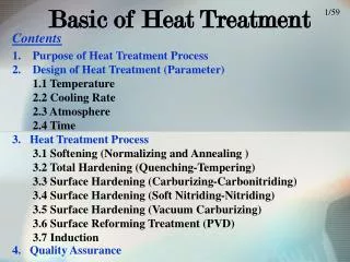
TECHNIQUES INVOLVE IN HEAT TREATMENT • ANNEALING • TEMPERING • QUENCHING • NORMALIZING • STRESS RELIEVING • SPHERODIZING
ANNEALING Annealing, process of heat treatment by which glass and certain metals and alloys are rendered less brittle and more resistant to fracture. Annealing minimizes internal defects in the atomic structure of the material and leaves it free from internal stresses that might otherwise be present because of prior processing steps. Ferrous metals and glass are annealed by heating them to high temperatures and cooling them slowly; copper and silver, however, are best annealed by heating and cooling quickly, then immersing in water.
TEMPERING Tempering, in metallurgy and engineering, low-temperature process in the heat treatment of steel by which a desirable balance is obtained between the hardness and toughness of the finished product. Steel articles that have been hardened by quenching, a process of heating to about 870° C (about 1600° F) and cooling rapidly in oil or water, become hard and brittle. Reheating to a lower temperature decreases the hardness somewhat but improves the toughness. The proper balance between hardness and toughness is controlled by the temperature to which the steel is reheated and the duration of the heating. This temperature is controlled by an instrument for measuring high temperatures, known as a pyrometer, or, historically, by observing the color of the oxide film formed on the metal during heating.
QUENCHING In materials science, quenching is the rapid cooling of a work piece to obtain certain material properties. It prevents low-temperature processes, such as phase transformations, from occurring by only providing a narrow window of time in which the reaction is both thermodynamically favorable and kinetically accessible. For instance, it can reduce crystallinity and thereby increase toughness of both alloys and plastics (produced through polymerization).
NORMALIZING Normalizing is a type of heat treatment applicable to ferrous metals only. It differs from annealing in that the metal is heated to a higher temperature and then removed from the furnace for air cooling. The purpose of normalizing is to remove the internal stresses induced by heat treating, welding, casting, forging, forming, or machining. Stress, if not controlled, leads to metal failure; therefore, before hardening steel, you should normalize it first to ensure the maximum desired results. Usually, low-carbon steels do not re- quire normalizing; however, if these steels are normalized, no harmful effects result. Castings are usually annealed, rather than normalized; however, some castings require the normalizing treatment.
STRESS RELIEVING Machining induces stresses in parts. The bigger and more complex the part, the more the stresses. These stresses can cause distortions in the part long term. For these reasons, stress relieving is often necessary. Stress relieving is done by subjecting the parts to a temperature of about 75 ºC (165 ºF) below the transformation temperature, line A1 on the diagram, which is about 727 ºC (1340 ºF) of steel—thus stress relieving is done at about 650 ºC (1202 ºF) for about one hour or till the whole part reaches the temperature. This removes more than 90% of the internal stresses. Alloy steels are stress relieved at higher temperatures. After removing from the furnace, the parts are air cooled in still air.
SPHERODIZING Any process of heating and cooling steel that produces a rounded or globular form of carbide. Thespheroidizing methods generally used are: a.) Prolonged heating at a temperature just below the lower critical temperature, usually followed by relatively slowcooling. b.) In the case of small objects of high carbon steels, the spheroidizing result is achieved more rapidly by prolongedheating to temperatures alternately within and slightly below the critical temperature range. c. Tool steel is generally spheroidized by heating to a temperature of 749°-804°C (1380° 1480°F) for carbon steels andhigher for many alloy tool steels, holding at heat from 1 to 4 hours, and cooling slowly in the furnace.