Download
1 / 38
380 likes | 585 Views
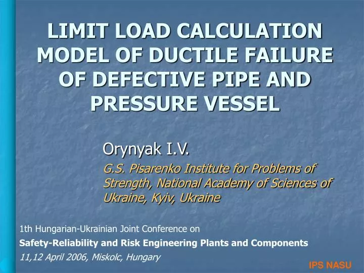
IPS NASU . LIMIT LOAD CALCULATION MODEL OF DUCTILE FAILURE OF DEFECTIVE PIPE AND PRESSURE VESSEL. Orynyak I.V. G.S. Pisarenko Institute for Problems of Strength, National Academy of Sciences of Ukraine, Kyiv, Ukraine. 1th Hungarian-Ukrainian Joint Conference on

E N D
IPS NASU LIMIT LOAD CALCULATION MODEL OF DUCTILE FAILURE OF DEFECTIVE PIPE AND PRESSURE VESSEL Orynyak I.V. G.S. Pisarenko Institute for Problems of Strength, National Academy of Sciences of Ukraine, Kyiv, Ukraine 1th Hungarian-Ukrainian Joint Conference on Safety-Reliability and Risk Engineering Plants and Components 11,12 April 2006, Miskolc, Hungary
2W 2a IPS NASU Application of Limit Load in Fracture Mechanics Thus another restriction (criterion) is needed
Ro Ri P N N t M M IPS NASU Examples of Limit Load Calculation
IPS NASU The Existing Formulas for Defected Pipes • c – defect halflength • l – defect halfwidth • a – defect depth • = 1-a/t - dimensionless ligament thickness = c / Rt - dimensionless length • 1 = c / Ra - dimensionless • length Battelle’s local 1 Battelle’s local 2 Nuclear Electric global - strength reduction cofficient
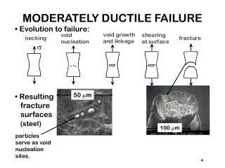
IPS NASU Strength Characteristic of Material Illustrating the viability of the UTS as a failure criterion for plastic collapse in a steel line pipe
IPS NASU Analytical Modeling of Ductile Failure • Static limit load theorem (lower bound) of the theory of plasticity: • an elastic–plastic structure will not collapse under monotone loads if • it is in static equilibrium and • the yield function is nowhere violated • Corollaries of the theorem : • Accounting for any additional bond in the body can only increase the limit load • Decreasing the volume of the body cannot increase the limit load • The solution which gives maximal value of limit load is more appropriate
IPS NASU AXIAL SURFACE CRACK IN A CYLINDER • 1. Assumptions: • shear force is equal to zero • shearing moments is equal to zero • axial force is proportional to the net-section 2. Equations of equilibrium 3. The Gist of the models The presence of an axial flaw causes imbalance between the circumferential stress and the internal pressure which must be balanced by the increment in the transverse forces to maintain equilibrium. The transverse forces, in turn, induce bending moments. The cylinder passes into the limit state when the bending moments reach a critical value corresponding to the chosen limit condition
IPS NASU AXIAL SURFACE CRACK IN A CYLINDER 4. Limit condition: where for crack-like defect 5. Second boundary of limit area, x = x1 . for rectangular form for semi-elliptical form for parabolic form
IPS NASU AXIAL SURFACE CRACK IN A CYLINDER 6. The maximum value of the applied moment: 7. The analytical formulas for rectangular form for semi-elliptical form for parabolic form
IPS NASU AXIAL SURFACE CRACK IN A CYLINDER Illustration of the stages of solution for the rectangular defect
IPS NASU AXIAL SURFACE CRACK IN A CYLINDER The crack shape influence on the dimensionless limit pressure: 1 - for a rectangular crack, 2 - for a semi-elliptical crack, 3 - for a parabolic crack
IPS NASU AXIAL SURFACE CRACK IN A CYLINDER The limit pressures for rectangular axial cracks as given by the different formulas: (I) “local” formula (1a), (II) “local” formula (1b), (III) “global” formula (2), (IV) – our solution (13a).
IPS NASU AXIAL SURFACE CRACK IN A CYLINDER Comparison with Battelle’s experimental results for defected pipes
t t н t t нс А В 2 k 2 L 2 L IPS NASU Q (x) x z z x THE TREATMENT OF THE MULTIPLE DEFECTS The strength reduction coefficient vs. the distance between adjacent defects The strength reduction coefficient is determined from
IPS NASU INFINITE DENT IN A THIN-WALLED PIPE 1. The form considered W << R – dent depth – jump in the angle of the tangent to the pipe surface 2. Equations of equilibrium
IPS NASU INFINITE DENT IN A THIN-WALLED PIPE 3. Applied moment determination 4. Limit condition where
IPS NASU INFINITE DENT IN A THIN-WALLED PIPE 5. Analytical results What is the characteristic dent dimension? - Elastic solution -“Elastic”
IPS NASU FINITE DENT IN A THIN-WALLED PIPE The base for analysis is that Finite length dent finite length crack • Rectangular dent if • if 2. “Parabolic” form if
IPS NASU AXIALLY SYMMETRIC DEFECT 1. Complete analogy with the “crack” solution 2. The only difference is the limit moments : 3. Limit condition: or 4. The solution for the limit pressure:
IPS NASU FINITE LENGTH FINITE WIDTH 3D DEFECT (SLOT) 1. Differential equation of equilibrium 2. “Slot” solution is between the “crack” and “axially sym.” solutions Mechanism of transferring the applied moments from sections to sections where
IPS NASU FINITE LENGTH FINITE WIDTH 3D DEFECT (SLOT) 3. Limit force and moments in circumferential direction h - optimization parameter and 4. Limit conditions in circumferential direction 5. Limit conditions in axial direction
IPS NASU FINITE LENGTH FINITE WIDTH 3D DEFECT (SLOT) Comparison of the calculated and experimental values of the fracture pressure for aluminum pipes with 3D defects
IPS NASU FINITE LENGTH FINITE WIDTH 3D DEFECT (SLOT)
IPS NASU THROUGH CRACK 1. Equilibriumdifferential equations 2. Boundary region On the boundaries On the boundaries
IPS NASU THROUGH CRACK 3. Redistribution axial stresses
IPS NASU THROUGH CRACK Redistribution axial stresses(epures)
IPS NASU THROUGH CRACK 4. Redistribution tangent stresses Determination
IPS NASU THROUGH CRACK Redistribution tangent stresses(epures)
IPS NASU THROUGH CRACK 5. Redistribution circumference stresses
IPS NASU THROUGH CRACK Redistribution circumference stresses (epures)
IPS NASU THROUGH CRACK 6. Limit state in the longitudinal direction Limit equilibrium equation of the moments for the determination of 7. Limit state in the circumferential direction Limit equilibrium equation of the moments
IPS NASU THROUGH CRACK 8. Comparison with the Battelle’s formula
IPS NASU THROUGH CRACK - experiment
IPS NASU THROUGH CRACK - experiment
IPS NASU Leak before break Precondition of the leak before break phenomenon - net thickness section The boundary between leak andbreak is obtained Then
IPS NASU Leak before break
IPS NASU Leak before break
IPS NASU CONCUSIONS • The limit load used in the criteria formulation of fracture mechanics originated from the theory of plasticity and should be treated by appropriate methods. • The theoretical models of ductile failure of defected bodies provides understanding of the ductile failure mechanisms, establishes the dimensionless parameters that have the most influence on the limit load. • Theoretical models can be used for choosing the analytical pattern in constructing empirical formulas and the checkpoints when performing the FEM calculations.