Download
1 / 37
380 likes | 594 Views
EKT 124 / 3 ELEKTRONIK DIGIT 1. CHAPTER 1 INTRODUCTION TO DIGITAL LOGIC. LOGIC GATES. NOT Gate (Inverter) AND Gate OR Gate NAND Gate NOR Gate X-OR and X-NOR Gates Fixed-function logic: IC Gates. Introduction(1)

E N D
EKT 124 / 3ELEKTRONIK DIGIT 1 CHAPTER 1 INTRODUCTION TO DIGITAL LOGIC
LOGIC GATES • NOT Gate (Inverter) • AND Gate • OR Gate • NAND Gate • NOR Gate • X-OR and X-NOR Gates • Fixed-function logic: IC Gates
Introduction(1) • All Logic circuit and functions are made from basic logic gates • Three basic logic gates: • AND gate – expressed by “ . ” • OR gate – expressed by “+” sign (NOTE: it is not an ordinary addition) • NOT gate – expressed by “ ’ “ or “¯”
Introduction(2) • Think about these logic gates as bricks in a structure. • Individuals bricks can be arranged to form various type of buildings, and bricks can be used to build fireplaces, steps, walls, walkways and floor. • Likewise, individual logic gates are arranged and interconnected to form various function in a digital system • There are several type of logic gates, just as there may be several shapes/sizes of bricks in a structure. By: Thomas L. Floyd & David M. Buchla
NOT Gate (Inverter) a) Gate Symbol & Boolean Equation b) Truth Table c) Timing Diagram
OR Gate a) Gate Symbol & Boolean Equation c) Timing Diagram b) Truth Table
AND Gate a) Gate Symbol & Boolean Equation b) Truth Table c) Timing Diagram
NAND Gate a) Gate Symbol, Boolean Equation & Truth Table b) Timing Diagram
NOR Gate a) Gate Symbol, Boolean Equation & Truth Table b) Timing Diagram
Exclusive-OR (XOR)Gate a) Gate Symbol, Boolean Equation & Truth Table b) Timing Diagram
Exclusive-NOR (XNOR)Gate XNOR 1 0 0 1 a) Gate Symbol, Boolean Equation
Universality of Gates(1) NAND Gate
Universality of Gates(2) NOR Gate
Examples : Logic Gates IC AND gate NOT gate Note : x is referring to family/technology (eg : AS/ALS/HCT/AC etc.)
Performance Characteristics and Parameters • Propagation delay Time • High-speed logic has a short pdt. • DC Supply Voltage (VCC) • Power Dissipation • Lower power diss. means less current from dc supply • Input and Output (I/O) Logic Levels • Speed-Power product • Fan-Out and Loading
BOOLEAN ALGEBRA • Boolean Operations & expression • Laws & rules of Boolean algebra • DeMorgan’sTheorems • Boolean analysis of logic circuits • Simplification using Boolean Algebra • Standard forms of Boolean Expressions • Boolean Expressions & truth tables • The KarnaughMap (K-Map) – SOP, POS, 5 Variables • Programmable Logic
Boolean Operations & expression • Expression: • Variable: a symbol used to represent logical quantities (1 or 0) • Eg.: A, B,..used as variable • Complement: inverse of variable and indicated by bar over variable • Eg.: Ā • Operation: • Boolean Addition – equivalent to the OR operation • Eg.: X = A + B • Boolean Multiplication – equivalent to the AND operation • Eg.: X = A∙B A X B A X B
Commutative Law of Addition Commutative law of addition, A+B = B+A the order of ORing does not matter.
Commutative Law of Multiplication Commutative law of Multiplication AB = BA the order of ANDing does not matter.
Associative Law of Addition Associative law of addition A + (B + C) = (A + B) + C The grouping of ORed variables does not matter
Associative Law of Multiplication Associative law of multiplication A(BC) = (AB)C The grouping of ANDed variables does not matter
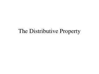
Distributive Law A(B + C) = AB + AC (A+B)(C+D) = AC + AD + BC + BD
Boolean Rules (1)1) A + 0 = A • Mathematically if you add O you have changed nothing • In Boolean Algebra ORing with 0 changes nothing
Boolean Rules (2)2) A + 1 = 1 • ORing with 1 must give a 1 since if any input is 1 an OR gate will give a 1
Boolean Rules (3)3) A • 0 = 0 • In math if 0 is multiplied with anything you get 0. If you AND anything with 0 you get 0
Boolean Rules (4)4) A • 1 = A • ANDing anything with 1 will yield the anything
Boolean Rules (5)5) A + A = A • ORing with itself will give the same result
Boolean Rules(6)6) A + A = 1 • Either A or A must be 1 so A + A =1
Boolean Rules(7)7) A • A = A • ANDing with itself will give the same result
Boolean Rules(8)8) A • A = 0 • In digital Logic 1 =0 and 0 =1, so AA=0 since one of the inputs must be 0.
Boolean Rules(9)9) A = A • If you NOT something twice you are back to the beginning
Boolean Rules(10)10) A + AB = A Proof: A + AB = A(1 + B) DISTRIBUTIVE LAW = A∙1 RULE 2: (1+B)=1 = A RULE 4: A∙1 = A
Boolean Rules(11)11) A + AB = A + B • If A is 1 the output is 1 , If A is 0 the output is B Proof: A + AB = (A + AB) + AB RULE 10 = (AA +AB) + AB RULE 7 = AA + AB + AA +AB RULE 8 = (A + A)(A + B) FACTORING = 1∙(A + B) RULE 6 = A + B RULE 4
Boolean Rules(12)12) (A + B)(A + C) = A + BC Proof: (A + B)(A +C) = AA + AC +AB +BC DISTRIBUTIVE LAW = A + AC + AB + BC RULE 7 = A(1 + C) +AB + BC FACTORING = A.1 + AB + BC RULE 2 = A(1 + B) + BC FACTORING = A.1 + BC RULE 2 = A + BC RULE 4