Download

1 / 6
60 likes | 233 Views
Light-Emitting Diodes. LED. Is the acronym for L ight- E mitting D iode, which is a semiconductor diode (a p-n junction) that emits light when positive current flows from the anode to the cathode of the LED. Anode is the p or positive side of the diode.

E N D
LED • Is the acronym for Light-Emitting Diode, which is a semiconductor diode (a p-n junction) that emits light when positive current flows from the anode to the cathode of the LED. • Anode is the p or positive side of the diode. • Cathode is the n or negative side of the diode.
Symbol • The symbol for the diode is an arrow head touching a vertical line. • The arrow shows the direction of current that will cause light to be emitted by the LED. • Occasionally, the symbol for an LED will also include arrows that represent light leaving the diode.
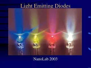
Discrete LEDs • The individual green, red, and yellow LEDs in the parts kit are called discrete LEDs. There is only one diode in each package. • Most of the package is not the actual LED, but wires and a plastic lens. • The longer lead on the package is the anode or p side of the diode. • The wire next to the flat on the package base is the cathode when looking at the LED from the bottom. LED chip Side view Bottom view
To Determine Anode and Cathode with your DMM • Switch your DMM to the diode symbol. • Place the red probe into the V-W plug and the black probe into the COM plug. • Place your probes across the diode. • If the result is a very small number, then your red probe is contacting the anode and the black probe is contacting the cathode of the diode. • If the result is an overload (overflow) condition, then the red probe is contacting the cathode and the black probe is contacting the anode of the diode.
Simulating a LED in PSpice There is no LED part in the student version of PSpice so we use a series combination of parts. • Dbreak (diode breakout part) • Allows current to flow when the voltage on the anode is 0.7V higher than the voltage on the cathode. • Vdc • Set to the difference in the voltage needed on the anode to turn the LED on • The yellowLEDs need at least 2V to turn on. • Note that the direction of the battery.