Download
1 / 30
300 likes | 608 Views
디지털공학 ( 선수과목 ) Digital Engineering 컴퓨터구조 Computer Architecture. Logic and Computer Design Fundamentals (Fourth Ed. 2008) M. Morris Mano & Charles R. Kime. Digital Engineering. 교재 : Logic and Computer Design Fundamentals ( 4 th ed. 2008 Mano) 영어 원서 , 한글 저서 ( 번역서 등 )

E N D
디지털공학 (선수과목)Digital Engineering컴퓨터구조Computer Architecture Logic and Computer DesignFundamentals(Fourth Ed. 2008) M. Morris Mano & Charles R. Kime
Digital Engineering 교재 : Logic and Computer Design Fundamentals (4th ed. 2008 Mano) 영어 원서, 한글 저서(번역서 등) digital circuit, digital circuit + digital computer 강의자료, 공지 : 홈페이지 konkuk.ac.kr konkuk.ac.kr/~ikpark, ikpark.konkuk.ac.kr, digcom.konkuk.ac.kr presentation 자료로 강의 :칠판 판서로 해달라? 받아 적는다고설명을 못 들음. 빠뜨리는 것 없게 하기 위해 PowerPoint 파일 .pptx : IE, chrome (google.co.kr) 대학 1년은 1년이 아니다. 확실하고 구체적인 목표를 정하라. 학점이 목적이 아니다 : 학점은 ? 실력도 아니다 →상대평가 Digital Engineering
Digital Engineering 예습 →강의시간 →복습 →다음 강의시간에 잠깐 복습, 질문 과제 : 각 chapter가 끝나면 problems → copy 하지 마라 혼자 힘으로 풀 수 있는 것만 풀어서 제출하라 할 때 제출 design project : HDL, FPGA 실습보드를 이용 개별 : combinational(3장, 4장) A 반 (3641): 월 9:00 ~ , B 반(3640): 월 10:30 ~ 상담 시간 : 강의 계획서, 재실(C동322호)일 때는 언제나 가능 공학인증관련 학교 개 강 : 사전설문조사(~2주) 중간고사 : 4월21일(월) 08:40~ 중간 " 기말고사 : 6월16일(월) 08:40~ 최종 " 강의평가 Digital Engineering
Digital Engineering analysis & design : digital (logic) circuit (system) digital system : store, move, process information manipulate two values logic : false, true electronic circuit : low, high voltage easy, simple number : 0, 1 → binary number combinational (Fig.), sequential (Fig.) circuit typical digital system : digital computer (Fig.) +v Digital Engineering
Digital Engineering human - decimal : digital system – binary conversion, encoding number system : decimal no. : 0~9 decimal digit binary no. : 0, 1 binary digit (bit) information representation : two : 1 bit → 21 = 2 0, 1 four : 2 bit → 22 = 4 00, 01, 10, 11 eight : 3 bit → 23 = 8 000 … 111 … rainbow : 7 → required 3 bit encoded 3 bit code • decimal binary • 0 0 • 1 1 • 2 10 • 3 11 • 4 100 • 5 101 • 6 110 • 7 111 • 8 1000 • 9 1001 • 10 1010 • 11 1011 • 12 1100 • 13 1101 • 14 1110 • 15 1111 2 digit 4 bit 0 000 0 000 0 00 0 00 0 0 0 0 0 0 0 0 0 0 Digital Engineering
Combinational Circuit digital system : combinational circuit, sequential circuit combinational circuits : consists of input variables, output variables, logic gates, interconnections outputs at any time : determined directly fromthe present combination of inputs without regard to previous inputs can be specified by atruth table also can be described byBoolean functions n input variables : 2npossible binary input combination m output : m Boolean functions Digital Engineering
Sequential Circuit interconnected combinational circuit, storage elements storage elements (Flip-Flops) : stored binary information outputs : are function not only inputs, but also present state of S.E. can be specified by a state table Digital Engineering
Memory Datapath Control unit CPU Inputs : keyboard, mouse, wireless, microphone Outputs : LCD, wireless, speakers Input/Output synchronous or asynchronous? Digital Computer • typical digital system : digital computer (Ch. 8,13) Ch. 9,10,11 (Ch. 5,7) (Ch. 9) (Ch. 12) Digital Engineering
More on the Generic Computer Digital Engineering
Digital Engineering analysis & design : digital (logic) circuit (system) analysis: digital circuit, inputs→ outputs using truth table (state table), Boolean expression, simulation tool design :inputs, outputs→ digital circuit ⇒ verification (analysis) air conditioner, heater, … input :toggle switch, output : LED(Light Emitting Diode), +v +v output inputs outputs digital circuit input : : push button switch, … 7-segment LED, … Digital Engineering
Digital Engineering design : gates (AND, OR, NOT, NAND, NOR, … ) : Ch.2 decoder, multiplexer : Ch.3 PLD (Programmable Logic Device, PROM, PLA, PAL) : Ch.6, custom IC : full custom IC, semi custom IC, FPGA (Field Programmable Gate Array) : 실습 gates : Digital Engineering
Digital Engineering decoder : CLC that performed decoding conversion of n-bit input code to m-bit output code with n≤m≤2n multiplexer : data selector CLC thatselects binary information from one of many input lines anddirects information to a single output line Digital Engineering
Digital Engineering PLD (Programmable Logic Device, PROM, PLA, PAL) : Digital Engineering
Digital Engineering FPGA (Field Programmable Gate Array) : 실습 HDL(Hardware Description Language) : VHDL, verilog HDL Altera DE2 development and education board : FPGA 실습보드Fig. Altera Cyclone II 2C35FPGA device : Altera design software : Quartus II web edition (9.0, 13.1) design circuit, pin assignment, simulation FPGA 실습보드 FPGA +v outputs inputs digital circuit +v : : pin Digital Engineering
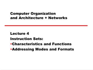
Logic and Computer Design Fundamentals Ch. 1 Digital Systems and Information Ch. 2 Combinational Logic Circuits Ch. 3 Combinational Logic Design Ch. 4 Arithmetic Functions and HDLs Ch. 5 Sequential Circuits Ch. 6 Selected Design Topics Ch. 7 Registers and Register Transfers Ch. 8 Memory Basics Ch. 9 Computer Design Basic Ch. 10 Instruction Set Architecture Ch. 11 RISC and CISC Central Processing Units Ch. 12 Input-Output and Communication Ch. 13 Memory Systems Digital Engineering Computer Architecture Digital Engineering
Digital Engineering Ch. 1 : Digital Systems and Information Ch. 2 : Combinational Logic Circuits Ch. 3 : Combinational Logic Design Ch. 4 : Arithmetic Functions and HDLs Ch. 5 : Sequential Circuits Ch. 6 : Selected Design Topics Digital Engineering
Computer Architecture Ch. 6 : Selected Design Topics Ch. 7 : Registers and Register Transfers Ch. 8 : Memory Basics Ch. 9 : Computer Design Basic Ch. 10 : Instruction Set Architecture Ch. 11 : RISC and CISC Central Processing Units Ch. 12 : Input-Output and Communication Ch. 13 : Memory Systems Digital Engineering
Digital Engineering Ch. 1 Digital Computers and Information 1-1 Information Representation 1-2 Number Systems 1-3 Arithmetic Operations 1-4 Decimal Codes 1-5 Alphanumeric Codes 1-6 Gray Codes Digital Engineering
Digital Engineering Ch. 2 Combinational Logic Circuits 2-1 Binary Logic and Gates 2-2 Boolean Algebra 2-3 Standard Forms 2-4 Two-Level Circuit Optimization 2-5 Map Manipulation 2-6 Pragmatic Two-Level Optimization 2-7 Multi-Level Circuit Optimization 2-8 Other Gate Types 2-9 Exclusive-OR Operator and Gates 2-10 High-Impedance Outputs Digital Engineering
Digital Engineering Ch. 3 Combinational Logic Design 3-1 Design Procedure 3-2 Beginning Hierarchical Design Space 3-3 Technology Mapping 3-4 Verification 3-5 Combinational Functional Blocks 3-6 Rudimentary Logic Functions 3-7 Decoding 3-8 Encoding 3-9 Selecting Digital Engineering
Digital Engineering Ch. 4 Arithmetic Functions and HDLs 4-1 Iterative Combinational Circuits 4-2 Binary Adders 4-3 Binary Subtraction 4-4 Binary Adder-Subtractors 4-5 Other Arithmetic Functions 4-6 Hardware Description Languages 4-7 HDL Representations – VHDL 4-8 HDL Representations – Verilog Digital Engineering
Digital Engineering Ch. 5 Sequential Circuits 5-1 Sequential Circuit Definition 5-2 Latches 5-3 Flip-Flops 5-4 Sequential Circuit Analysis 5-5 Sequential Circuit Design 5-6 Other Flip-Flop Types 5-7 State-Machine Diagrams and Applications 5-8 HDL Representation for Sequential Circuits – VHDL 5-9 HDL Representation for Sequential Circuits – Verilog Digital Engineering
Digital Engineering Ch. 6 Selected Design Topics 6-1 The Design Space 6-2 Gate Propagation Delay 6-3 Flip-Flop Timing 6-4 Sequential Circuit Timing 6-5 Asynchronous Interactions 6-6 Synchronization and Metastability 6-7Synchronous Circuit Pitfalls 6-8 Programmable Implementation Technologies Digital Engineering
Digital Engineering Ch. 7 : Registers and Register Transfers 7-1 Registers and Load Enable 7-2 Register Transfers 7-3 Register Transfer Operations 7-4 A Note for VHDL and Verilog Users Only 7-5 Microoperations 7-6 Microoperations on a Single Register 7-7 Register Cell Design 7-8 Multiplexer and Bus-Based Transfers for Multiple Reg.s 7-9 Serial Transfer and Microoperations 7-10 Control of Register Transfer 7-11 HDL Representation for Shift Registers and Counters-VHDL 7-12 HDL Representation for Shift Registers and Counters-verilog 7-13 Microprogrammed Control Digital Engineering
Altera DE2 development and education board Digital Engineering
Altera DE2 development and education board Digital Engineering
Altera DE2 development and education board Altera DE2 development and education board : FPGA 실습보드Fig. Altera Cyclone II 2C35FPGA device : Fig. 33,216 LEs 105 M4K RAM Blocks(4Kbits + 512 parity bits) : 483,840 total RAM bits 35 embedded multipliers(two 9х9-bit or one 18х18-bit multiplier) 4 PLLs(phase-locked loop) 475 user I/O pins (672-pin package) Altera design software : Quartus II (9.0, 13.1) Web edition VHDL, Verilog HDL, schematic diagram, state diagram simulation Digital Engineering
Cyclone II device block diagram Digital Engineering
Cyclone II device block diagram Digital Engineering
Programmable Implementation Technologies Digital Engineering