Download
1 / 70
780 likes | 1.26k Views
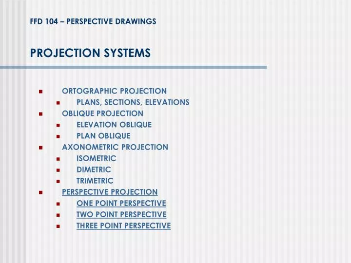
PROJECTION SYSTEMS. FFD 104 – PERSPECTIVE DRAWINGS. ORTOGRAPHIC PROJECTION PLANS, SECTIONS, ELEVATIONS OBLIQUE PROJECTION ELEVATION OBLIQUE PLAN OBLIQUE AXONOMETRIC PROJECTION ISOMETRIC DIMETRIC TRIMETRIC PERSPECTIVE PROJECTION ONE POINT PERSPECTIVE TWO POINT PERSPECTIVE

E N D
PROJECTION SYSTEMS FFD 104 – PERSPECTIVE DRAWINGS • ORTOGRAPHIC PROJECTION • PLANS, SECTIONS, ELEVATIONS • OBLIQUE PROJECTION • ELEVATION OBLIQUE • PLAN OBLIQUE • AXONOMETRIC PROJECTION • ISOMETRIC • DIMETRIC • TRIMETRIC • PERSPECTIVE PROJECTION • ONE POINT PERSPECTIVE • TWO POINT PERSPECTIVE • THREE POINT PERSPECTIVE
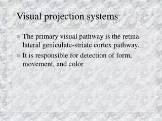
PERSPECTIVE PROJECTION FFD 104 – PERSPECTIVE DRAWINGS 1-point perspective: One horizontal axes is perpendicular to the picture plane, the other horizontal axis and the vertical axis are parallel with the picture plane. 2-point perspective: Both horizontal axes are oblique to the picture plane, and the vertical axis remains parallel with the picture plane. 3-point perspective: Both horizontal axes as well as the vertical axes are oblique to the picture plane.
MAIN ELEMENTS OF PERSPECTIVE DRAWINGS FFD 104 – PERSPECTIVE DRAWINGS PICTURE PLANE:It is an imaginary transparent plane on which the image of a 3D object is projected. It is always perpendicular to the central axis of vision. SIGHTLINES:Lines that project from the standing point to points that are viewed. PERSPECTIVE PROJECTION: The projection of the real object on the picture plane. CENTRAL AXIS OF VISION: It is the sightline determining the direction in which the observer is assumed to be looking. THE STATION POINT (SP):The fixed point in space representing a single eye of the observer.
MAIN ELEMENTS OF PERSPECTIVE DRAWINGS FFD 104 – PERSPECTIVE DRAWINGS (HL) HORIZON LINE:The line representing the intersection of the picture plane (PP) and a horizontal plane passing through the station point (SP). (C) CENTER OF VISION:It is the point on horizon line at which the central axis of vision intersects the Picture Plane. (GP) GROUND PLANE:The horizontal plane of reference from which heights can be measured. (GL) GROUND LINE:Horizontal line representing the intersection of GP and PP. The distance from GL to HL is equal to the height of the SP above GP
THE CONE OF VISION FFD 104 – PERSPECTIVE DRAWINGS The cone of vision describes the sightlines radiating outward from SP and forming an angle with CAV in linear perspective. It serves as a guide to determine what is to be included within the boundaries of perspective drawing. A 60° cone of vision is assumed to be the normal field of vision. To minimize distortion of circles and circular shapes, they should fall within a 30° cone of vision. A 90° cone of vision is acceptable for peripheral elements.
ONE POINT PERSPECTIVE FFD 104 – PERSPECTIVE DRAWINGS If we view a cube with our central axis of vision (CAV) perpndicular to one of its faces, all of the cubes vertical lines are parallel with the picture plane (PP) and remain vertical. The horizontal lines that are parallel with PP and perpendicular to CAV also remain horizontal. The lines that are parallel with CAV, however will appear to converge at the center of vision (C).
ONE POINT PERSPECTIVE FFD 104 – PERSPECTIVE DRAWINGS • Vertical lines are parallel with the picture plane (PP) and remain vertical. - The horizontal lines that are parallel with PP and perpendicular to CAV also remain horizontal. - The lines that are parallel with CAV and perpendicular to the picture pane PP, however will appear to converge at the center of vision (C).
ONE POINT PERSPECTIVE FFD 104 – PERSPECTIVE DRAWINGS
SAMPLES FROM PAINTINGS FFD 104 – PERSPECTIVE DRAWINGS
SAMPLES FROM PAINTINGS FFD 104 – PERSPECTIVE DRAWINGS “The Ideal City”, attributed to Piero della Francesca, 1480s
SAMPLES FROM PAINTINGS FFD 104 – PERSPECTIVE DRAWINGS Carlo Crivelli, “The Annunciation”, 1486
SAMPLES FROM PAINTINGS FFD 104 – PERSPECTIVE DRAWINGS Raphael,“The School of Athens”, 1510-1511
SAMPLES FROM PAINTINGS FFD 104 – PERSPECTIVE DRAWINGS Leonardo da Vinci, “The Last Supper”, 1498
SAMPLES FROM PAINTINGS FFD 104 – PERSPECTIVE DRAWINGS Andrea Pozzo, “Glory of Saint Ignatius”, 1691-94 ceiling fresco in The Church of Saint Ignazio, Rome, ITALY