Download
1 / 27
270 likes | 278 Views
Free Space Optical Data Links. B. Fernando, P.M. DeLurgio, R. Stanek, B. Salvachua, D. Underwood ANL-HEP D. Lopez ANL Center for Nanoscale Materials. Our Original Motivation. ATLAS/CMS: from design to reality. Amount of material in ATLAS and CMS inner trackers. Weight: 3.7 tons.

E N D
Free Space Optical Data Links B. Fernando, P.M. DeLurgio, R. Stanek, B. Salvachua, D. Underwood ANL-HEP D. Lopez ANL Center for Nanoscale Materials
Our Original Motivation ATLAS/CMS: from design to reality Amount of material in ATLAS and CMS inner trackers Weight: 3.7 tons Weight: 4.5 tons • Active sensors and mechanics ~ 10% of material budget • 70 kW power into tracker and to remove similar amount of heat • Very distributed heat sources and power-hungry electronics inside volume • complex layout of services, most of which were not at all understood at the time of the TDRs 2
Technologies • In the long run, Optics will be used for everything because of bandwidth. • In the long run, modulators will be used instead of modulated lasers (e.g. VCSELs) because of Bandwidth (no chirp), Low Power, and Reliability. • There are known Rad-Hard Modulators. • LiNO3 is in common usage, and has been tested for radiation hardness by several HEP groups. The only disadvantage for LiNO3 is size, (few cm long) • The IBM Mach-Zehnder in Silicon and the MIT absorption modulator in Silicon/ Germanium should be rad hard. We have tested the Si/Ge material in an electron beam at Argonne. These small modulators can in principle be integrated into CMOS chips. • Many systems working at >~ 10 Gb/s already use modulators and CW lasers. • Modulators enable one to get the lasers out of tracking. 3
Concept of communication between ID layers for trigger decisions Some concepts for interlayer communication for input to trigger decisions A major improvement beyond even the conventional form of optical links could be made by using optical modulators so that the lasers are not in the tracking volume.
Technology : Modulators Cooling Cooling Cooling Power (~10 mA /channel) Signal wires Detecting element Controller Detecting element controller Power VCSEL Driver Fiber CW laser Commercial VCSEL signal 3 different components Could integrate in the same die ! PIN diode signal Fiber PIN diode Inside Outside Fiber Inside Outside • Advantages: • High bandwidth: no chirp, no wires from detectors commercial systems work >10 Gb/s/channel • Low material budget: Less Power inside detector fewer wires needed less cooling needed • Higher reliability: Laser sources outside the detector, modulators can be integrated into a single die, don’t need separate high current drivers, No high current density devices (VCSEL), less radiation/ESD sensitivity Modulators vs VCSELs 7
Technology : Absorption Modulators MIT Design of GeSi EAM Device Structure a-Si GeSi a-Si on a-Si GeSi a-Si off Tapered vertical coupler • Fabricated with 180 nm CMOS technology • Small footprint (30 µm2) • Extinction ratio: 11 dB @ 1536 nm; 8 dB at 1550 nm • Operation spectrum range 1539-1553 nm (half of the C-band) • Ultra-low energy consumption (50 fJ/bit, or 50 µW at 1Gb/s) • GHz bandwidth • 3V p-p AC, 6 V bias • Same process used to make a photodetector Liu et al, Opt. Express. 15, 623-628 (2007) 8
Technology : Mach-Zehnder Modulators 41 mW at 5 Gb/sec 100 u long x 10 u wide Thin, order u Broad spectrum 7.3 nm at 1550 80 u long delay line internal 1V p-p AC, 1.6V bias 9
Advances are Needed in Modulators for use in HEP Active device Approx. 1 Gram • We presently use LiNO3 modulators – fast, rad hard, but not small • MIT and IBM have prototypes of modulators to be made inside CMOS chips • It would cost us several x $100k for 2 foundry runs to make these for ourselves • There are commercial modulators of small size, but some are polymer (not rad hard) and some are too expensive at the present time • We may have found a vendor (Jenoptik) for small Modulators who will work with us on ones which can be wire-bonded and have single-mode fiber connections • Need to test for radiation hardness of these 10
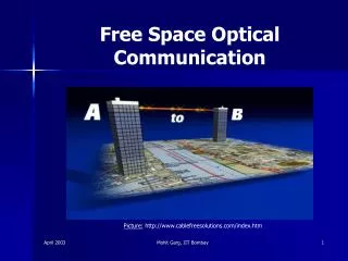
Technology : Free Space Data Links • Advantages: • Low Mass • No fiber routing (c.f. CMS 40K fibers to route) • Low latency (No velocity factor) • Low delay drift (No thermal effects such as in fibers) • Work over distances from few mm (internal triggers) to ~Km (counting house) or far ( to satellite orbit) 11
Technology : MEMS Mirrors A commercially available MEMS mirror (Developed at ARI, Berkeley) The Lucent Lambda Router: 12
Technology : Argonne MEMS Mirrors • Argonne Center for NanoScale Materials, CNM, has designed and simulated novel MEMS mirrors that should solve the problems of commercial mirrors • The mirror is supported laterally and it can be actuated using 4 torsional actuators located in the vicinity. • More stable mirror with better mechanical noise rejection. • Under fabrication and we expect to have them available for testing very soon. The figures show a 3D finite element analysis of the MEMS designed. The left panel shows the top view of the mirror and the right panel a bottom view. 13
ANL Concept of Direct Feedback to Establish and Maintain Stable Alignment 14
Studies of Direct Feedback Concept • The commercial MEMS mirrors have ~40 dB resonance peaks at 1 and 3 KHz. • To use the direct feedback, developed an inverse Chebyshev filter which has a notch at 1 kHz, and appropriate phase characteristics (Left Figure) • With the filter we were able to make the beam follow a reflecting lens target within about 10 μm when the target moved about 1 mm (Right Figure). • Still has some fundamental issues at large excursion (~1 cm) • A separate feedback link solves this issue A test setup used to demonstrate MEMS mirror steering with an analog control loop which compensates for the mirror resonances at 1 and 3 KHz. The amplitude-frequency map of our analog feedback loop, demonstrating phase stability at 100 Hz. 15
Beams in Air: Size vs Distance Due to diffraction, there is an optimum diameter for a beam for a given distance in order to reduce 1/r2 losses • The Rayleigh distance acts much like Beta-Star in accelerators • Relates waist size and divergence • Depends on wavelength • If we start with a diameter too small for the distance of interest, the beam will diverge, and will become 1/r2 at the receiver, and we will have large losses (We can still focus what we get to a small device like an APD or PIN diode ). This is typical of space, Satellite, etc. applications. • If we start with an optimum diameter, the waist can be near the receiver, and we can capture almost all the light and focus it to a small spot • Examples, ~ 1 mm for 1 m, ~ 50 mm for 1 Km
Short/long distance • Extreme low mass • Very high speed • Radiation hardness • Reliability • LiNO3 Modulators + fibers • Mach-Zehnder Modulators + fibers • Same die Mach-Zehnder Modulators + fibers • Modulators + free space links for short distances • Modulators + free space links for long distances • Modulators + free space links + trigger Applications
Applications short distances
Our Current Version Reflective lens Reflection 850 nm LASER For alignment This Assembly moves X optical electric ADC TIA SFP Rigid Coupling Y Si Detectors SPI Small Prism GRIN lens to Capture wires FPGA Bit Error Tester FPGA 1550 LASER Beam Lookup table Digital filter SPI wires X Asphere Lens to launch MEMS Mirror to steer DAC Amp Y Modulator CW LASER 1550 nm 19
Digital Processing MEMS Steering Setup MEMS Mirror Quad Detector and Steering Laser RECEIVER Reflecting Lens Launch Lens GRIN LENS To Fiber Modulator Standard Fiber Receiver FPGA Pseudo Random Data, Bit Error Rate 20
Applications Long distances
ANL Long Range Free-Space Communication Telescope 1 Gb/s over 80 Meters 22
Advances Made at Argonne • Steering using reflections from the receiver system, without wires. We made a major improvement by separating data link and the alignment link. • Found ways to form beams and receive beams that reduce critical alignments, reducing time and money for setup. • 1.25 Gb/s over 1550 nm in air, using a modulator to impose data, and FPGA to check for errors, <10-14error rate, with targetmoving about 1 cm x 1 cm at 1 m. • Control of MEMS mirror which has high Q resonance (using both Analog and Digital filter) • Long range data Telescope using low power (0.5 mW vs 250 mW commercial) by means of near diffraction limited beams • Some radiation testing of SiGe Modulator Material 23
Future Directions • Develop at least a 5 Gb/s link in air (with digital feedback) • More robust long distance optical link • Evaluate • MEMS mirror supplied by Argonne CNM • Commercial modulators • In addition, we have submitted a proposal to apply optical readout to an actual detector in the Fermilab test beam using Argonne DHCAL, which would be an ideal test-bed with 400K channels.
New optical technology for low mass intelligent trigger and readout, D. Underwood, B. Salvachua-Ferrando, R. Stanek, D. Lopez, J. Liu, J. Michel, L. C. Kimmerling, JINST 5 C0711 (2010) Development of Low Mass Optical Readout for High Data Bandwidth Systems”, D. Underwood, P. DeLurgio, G. Drake, W. Fernando, D. Lopez, B. Salvachua-Ferrando, and R. Stanek, IEE/NSS Knoxville, September 2010. INNOVATIONS IN THE CMS TRACKER ELECTRONICS G. Hall, http://www.technology.stfc.ac.uk/.../geoff%20electronics%20why%20TrackerRO_1.doc The IBM Mach-Zender: Paper by Green, et al in Optics Express Vol 5, No 25, December 2007 http://www.photonics.com/Content/ReadArticle.aspx?ArticleID=32251 THE MIT DEVICE: Paper by Liu, et al. as described in Nature Photonics, December, 2008 http://www.nature.com/nphoton/journal/v2/n7/pdf/nphoton.2008.111.pdfhttp://www.nature.com/nphoton/journal/v2/n7/pdf/nphoton.2008.99.pdf MEMS mirrors: “Monolithic MEMS optical switch with amplified out-of-plane angular motion”,D. Lopez, et al, IEEE Xplore 0-7803-7595-5/02/ “The Lucent LambdaRouter”, D.J.Bishop, et al, IEEE Communications Magazine, 0163-6804/02/
Radiation hardness references Radiation hardness of LiNO3: CERN RD-23 PROJECT Optoelectronic Analogue Signal Transfer for LHC Detectors , http://rd23.web.cern.ch/RD23/ and http://cdsweb.cern.ch/record/315435/files/cer-0238226.pdf Radiation Hardness evaluation of SiGe HBT technologies for the Front-End electronics of the ATLAS Upgrade”, M. Ullan, S.Diez, F. Campabadal, M.Lozano, G. Pellegrini, D. Knoll, B. Heinemann, NIM A 579 (2007) 828 “Silicon-Germanium as an Enabling IC Technology for Extreme Environment Electronics,” J.D. Cressler, Proceedings of the 2008 IEEE Aerospace Conference,” pp. 1-7 (on CD ROM), 2008. http://www-ppd.fnal.gov/eppoffice-w/Research_Techniques_Seminar/ Talks/Cressler_SiGe_Fermilab_6-9-09.pdf