Download
1 / 41
410 likes | 412 Views
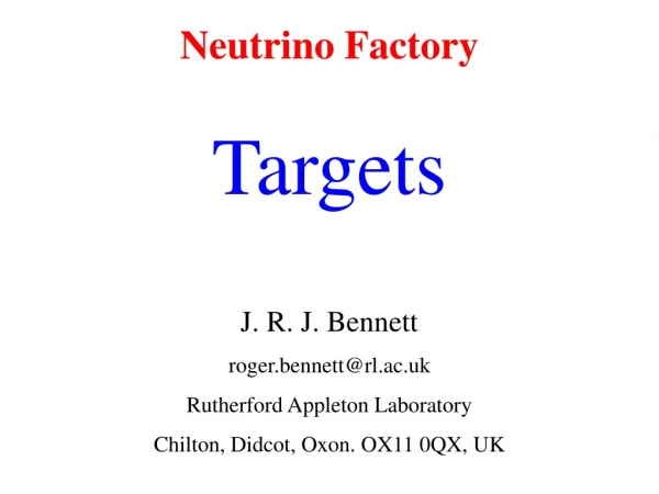
Large SOLID TARGETS for a Neutrino Factory J. R. J. Bennett Rutherford Appleton Laboratory roger.bennett@rl.ac.uk. Note. In all cases I will refer to the power in the target rather than the beam.

E N D
Large SOLID TARGETS for a Neutrino Factory J. R. J. Bennett Rutherford Appleton Laboratory roger.bennett@rl.ac.uk
Note. • In all cases I will refer to the power in the target rather than the beam. • Thus, in the case of the neutrino factory, a 1 MW target has 1 MW dissipation and the beam power is 4 MW. • I will not talk about liquid metal targets.
Contents 1. Solid target review -- or Why are we afraid of solid targets? 2. Proposed R&D in the UK
target protons Typical Schematic Arrangement of a Neutrino Factory Target
2 cm 20 cm Target Heavy metal - Tantalum Beam hits the whole target Not a stopping target
SOLID Targets Need to remove the heat - 1 MW BUT The PERCIEVED problem is SHOCK WAVES
Shock Shock processes are encountered when material bodies are subjected to rapid impulse loading, whose time of load application is short compared to the time for the body to respond inertially. R A Graham in High-Pressure Shock Compression of Solids. Ed. J R Asay & M Shahinpoor, Springer-Verlag, 1992
The processes are all non linear so mathematical description is complex. Further, discontinuities complicate solution. Thus specialised techniques have been constructed to render the problem mathematically tractable. Neil Bourne, RMCS, Shrivenham private communication
Examples of Shock Events: • Explosions • Bullets Impacting • Volcanic Eruptions • Meteor Collisions • Aircraft Sonic Boom
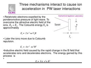
Simple explanation of shock waves Short pulse of protons Short pulse of protons target 2d Time t = 0 inertia prevents the target from expanding until: t > 0 Δd End velocity the temperature rises by ΔT and the target expands by Δd (axially) v is the velocity of sound in the target material; a is the coefficient of linear expansion
End velocity Where: v is the velocity of sound in the target material a is the coefficient of linear expansion q is the energy density dissipated (J g-1) C is the specific heat (J g-1)
The velocity of sound is given by, where E is the modulus of elasticity and r the density Thus the end velocity becomes, To minimise V, for a given q, select a material with: a & E small; C & r large. (Super-Invar has a very small a but losses this property under irradiation)
Hence the momentum of the end of the target can be found. • Since the force is equal to the rate of change of momentum it is possible to calculate the stress in the material. • In the case of the Neutrino factory target the stress exceeds the strength –disaster. • Can make a better analysis - Peter Sievers, under ideal elastic conditions, CERN Note LAB.II/BT/74-2, 1974. • There are modern stress analysis packages available commercially to deal with dynamic situations. • Chris Densham has calculated (ANSYS) that a solid tantalum target for the neutrino factory will probably show signs of shock fracture after a few pulses.
Shock, Pulse Length and Target Size If we heat a target uniformly and slowly – there is no shock! Or, when the pulse length t is long compared to the time t taken for the wave to travel across the target – no shock effect! So, if we make the target small compared to the pulse length there is no shock problem. If No problem! Assume t = 2 ms, V = 3.3x105 cm s-1 , then d = 0.7 cm Also need sufficient pulsed energy input.
This principle has been used in the target designed by Peter Seivers (CERN). • Solid Metal Spheres in Flowing Coolant • Small spheres (2 mm dia.) of heavy metal are cooled by the flowing water, liquid metal or helium gas coolant. • The small spheres can be shown not to suffer from shock stress (pulses longer than ~3 ms) and therefore be mechanically stable.
Looks like we have a problem for large targets! (2 cm diameter, 20 cm long)
BUT! Have we seen shock wave damage in solid targets?
What do we know? There are a few pulsed (~1ms) high power density targets in existence: Pbar – FNAL NuMI SLAC (electrons)
No damage with ISOLDE (foil) or ISIS targets; but some damage with Pbar targets. In 2 tests on solid tantalum bars (20 cm long 1 cm diameter) at ISOLDE Jacques Lettry has observed severe distortion. He considers this is due to shock.
Stack of slowly rotating discs Gas cooling between discs proton beam pbar target Schematic Diagram of the Pbar target
Section through the pbar target assembly Vinod Bharadwaj / Jim Morgan
copper cooling discs Pbar Target (Jim Morgan) nickel copper copper rhenium aluminium
Proposed R&D in the UK • Radiation cooled rotating toroid • Calcuate levitation drive and stabilisation system • Build a model of the levitation system • Individual bars • Calculate mechanics of the system • Model system • Calculate the energy deposition, radio-activity for the target, solenoid magnet and beam dump. • Calculate the pion production (using results from HARP experiment) and calculate trajectories through the solenoid magnet.
Proposed R&D, Continued • 4. Model the shock • a) Measure properties of tantalum at 2300 K • b) Model using hydrocodes developed for explosive applications at LANL, LLNL, AWE etc. • c) Model using dynamic codes developed by ANSYS • 5. Continue electron beam tests on thin foils, improving the vacuum • 6. In-beam test at ISOLDE - 106 pulses • 7. In-beam tests at ISIS – 109 pulses
Schematic diagram of the rotating toroidal target rotating toroid toroid magnetically levitated and driven by linear motors solenoid magnet toroid at 2300 K radiates heat to water-cooled surroundings proton beam
Heat Dissipation by Thermal Radiation This is very effective at high temperatures due to the T4 relationship
POWER DISSIPATION 3 1 10 10000 m v = 100 m/s 1000 m 100 2000 m v = 20 m/s 100 m 200 m v = 10 m/s 1000 m 10 power MW 20 m 100 m 10 m v = 1 m/s 10 m 100 m 2 m 1 10 m v = 0.1 m/s 1 m 1 m 10 m 0.1 1 m 0.1 m 0.1 m 0.01 3 0.01 0.1 1 10 100 1 10 radius/velocity
Temperature Rise v Velocity at Different Powers 4 1 10 Power MW 3 1 10 T, K 10 100 6 3 1 10 1 0.1 0.1 0.01 4 0 1000 2000 3000 4000 5000 6000 7000 8000 9000 1 10 50Hz 100 Hz velocity, (V = l f), cm/s for l = 20 cm
Target Designs • Toroid • If the toroid breaks there are problems. • Individual bars are better • 2. Bars on a wheel • - Problems with the solenoid magnet • 3. Free bars
vacuum box Wheel Target 1MW Target Dissipation (4 MW proton beam) tantalum or carbon radiation cooled temperature rise 100 K speed 5.5 m/s (50 Hz) diameter 11 m spoke drive shaft protons target solenoid coils
Individual free targets Levitated target bars are projected through the solenoid and guided to and from the holding reservoir where they are allowed to cool. proton beam solenoid collection and cooling reservoir
V = Lf R governed by power V Threading solenoid Individual Targets suspended from a Guide Wire
Choice of Target Material Tantalum Why?
Why Tantalum? • Refractory. Melting point 3272 K • Good irradiation properties • No damage observed with ISIS tantalum target after bombardment with 1.27x10²¹ protons/cm2, suffered 11 dpa. No swelling. Increased yield strength. No cracking. Remains very ductile. Hardness increased by a factor <2. [J. Chen et al, J. Nucl. Mat. 298 248-254 (2001)] • 3. Relatively easy to machine and weld etc.